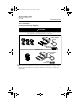
4593_Rev_BA.fm Page 1 Friday, August 7, 2009 3:38 PM Quick Installation Guide 00825-0100-4593, Rev BA July 2009 Rosemount 1151 Rosemount 1151 Pressure Transmitter with 4-20 mA HART Protocol P r oduc tDi s c ont i nue d Start Step 1: Mount the Transmitter Step 2: Consider Housing Rotation Step 3: Connect the Wiring and Power Up Step 4: Set Switches Step 5: Configuration Step 6: Trim the Transmitter Product Certifications End www.rosemount.
4593_Rev_BA.fm Page 2 Friday, August 7, 2009 3:38 PM Quick Installation Guide 00825-0100-4593, Rev BA July 2009 Rosemount 1151 WARNING Explosions could result in death or serious injury: Installation of this transmitter in an explosive environment must be in accordance with the appropriate local, national, and international standards, codes, and practices. Please review the approvals section of the 1151 reference manual for any restrictions associated with a safe installation.
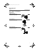
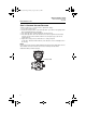
4593_Rev_BA.fm Page 3 Friday, August 7, 2009 3:38 PM Quick Installation Guide 00825-0100-4593, Rev BA July 2009 Rosemount 1151 STEP 1: MOUNT THE TRANSMITTER A. Applications Liquid Flow Applications 1. Place taps to the side of the line. 2. Mount beside or below the taps. Flow Gas Flow Applications 1. Place taps in the top or side of the line. 2. Mount beside or above the taps. Flow Steam Flow Applications 1. Place taps to the side of the line. 2. Mount beside or below the taps. 3.
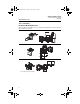
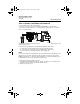
593_Rev_BA.fm Page 4 Friday, August 7, 2009 3:38 PM Quick Installation Guide 00825-0100-4593, Rev BA July 2009 Rosemount 1151 STEP 1 CONTINUED... B. Optional Mounting Brackets When installing the transmitter to one of the optional mounting brackets, torque the bracket bolts to 125 in.-lbs. (0,9 N-m). Pipe Mount Panel Mount(1) Flat Mount (1) 4 Panel bolts are customer supplied.
4593_Rev_BA.fm Page 5 Friday, August 7, 2009 3:38 PM Quick Installation Guide 00825-0100-4593, Rev BA July 2009 Rosemount 1151 STEP 1 CONTINUED... C. O-rings with Flange Adapters WARNING Failure to install proper flange adapter O-rings may cause process leaks, which can result in death or serious injury. The two flange adapters are distinguished by unique O-ring grooves. Only use the O-ring that is designed for its specific flange adapter, as shown below.
4593_Rev_BA.fm Page 6 Friday, August 7, 2009 3:38 PM Quick Installation Guide 00825-0100-4593, Rev BA July 2009 Rosemount 1151 STEP 2: CONSIDER HOUSING ROTATION To improve field access or to better view the optional LCD display: 1. Loosen the housing lock nut. 2. Rotate the housing clockwise to the desired position – up to 90° from its original position. Over rotating will damage the transmitter. 3. If the desired position is attained, tighten the housing lock nut. 4.
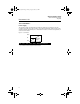
4593_Rev_BA.fm Page 7 Friday, August 7, 2009 3:38 PM Quick Installation Guide 00825-0100-4593, Rev BA July 2009 Rosemount 1151 STEP 3: CONNECT THE WIRING AND POWER UP Use the following steps to wire the transmitter: 1. Remove the housing cover on the side marked TERMINALS on the nameplate. 2. Connect the positive lead to the “+” terminal and the negative lead to the “–” terminal. Figure 1.
4593_Rev_BA.fm Page 8 Friday, August 7, 2009 3:38 PM Quick Installation Guide 00825-0100-4593, Rev BA July 2009 Rosemount 1151 STEP 3 CONTINUED... Power Supply The dc power supply should provide power with less than two percent ripple. The total resistance load is the sum of the resistance of the signal leads and the load resistance of the controller, indicator, and related pieces. Note that the resistance of intrinsic safety barriers, if used, must be included. Figure 2.
4593_Rev_BA.fm Page 9 Friday, August 7, 2009 3:38 PM Quick Installation Guide 00825-0100-4593, Rev BA July 2009 Rosemount 1151 STEP 4: CONFIGURE THE TRANSMITTER Failure Mode Alarm Switch 1. Remove the housing cover. 2. Locate the failure mode switch (see Figure 3). 3. Move the switch to the desired alarm setting. To set the failure mode to high alarm, position the switch toward “HI.” To set the failure mode to low alarm, position the switch to “LO.” 4. Replace the housing cover.
4593_Rev_BA.fm Page 10 Friday, August 7, 2009 3:38 PM Quick Installation Guide Rosemount 1151 00825-0100-4593, Rev BA July 2009 STEP 5: CALIBRATE THE TRANSMITTER Verify Transmitter Configuration NOTE: A check (✓) indicates the basic configuration parameters. At minimum, these parameters should be verified as part of the configuration and startup procedure. Table 1.
4593_Rev_BA.fm Page 11 Friday, August 7, 2009 3:38 PM Quick Installation Guide 00825-0100-4593, Rev BA July 2009 Rosemount 1151 STEP 5 CONTINUED... Configure LCD Display Figure 4. Sample 1151 LCD Display Digital Bar Graph Left Configuration Button Retaining Ring Right Configuration Button NOTE The LCD display time-out is approximately 16 seconds. If keys are not pressed within this period, the indicator reverts to reading the signal. Position the Decimal Point and Select the Meter Function 1.
4593_Rev_BA.fm Page 12 Friday, August 7, 2009 3:38 PM Quick Installation Guide Rosemount 1151 00825-0100-4593, Rev BA July 2009 STEP 5 CONTINUED... Set the Display Equivalent to a 4 mA Signal 1. Unscrew the retaining ring shown in Figure 4 and remove the LCD display cover. 2. Press the left button for two seconds. 3. To decrement the display numbers, press the left configuration button and to increment the numbers, press the right configuration button. Set the numbers between –999 and 1000. 4.
4593_Rev_BA.fm Page 13 Friday, August 7, 2009 3:38 PM Quick Installation Guide 00825-0100-4593, Rev BA July 2009 Rosemount 1151 STEP 6: TRIM THE TRANSMITTER NOTE Transmitters are shipped fully calibrated per request or by the factory default of full scale (span = upper range limit). Full Trim A full trim is a two-point sensor calibration where two end-point pressures are applied, and the transmitter process variable output is adjusted to agree with the pressure input.
4593_Rev_BA.fm Page 14 Friday, August 7, 2009 3:38 PM Quick Installation Guide Rosemount 1151 00825-0100-4593, Rev BA July 2009 STEP 6 CONTINUED... Using the Transmitter Zero Adjustment Buttons Perform the following steps to perform a rerange using the zero adjustment buttons (see Figure 3). 1. Apply a pressure equivalent to the lower calibrated value on the high side of the transmitter. 2. Remove the circuit side cover to expose the span and zero buttons.
4593_Rev_BA.fm Page 15 Friday, August 7, 2009 3:38 PM Quick Installation Guide 00825-0100-4593, Rev BA July 2009 Rosemount 1151 PRODUCT CERTIFICATIONS Approved Manufacturing Locations Rosemount Inc. — Chanhassen, Minnesota, USA Fisher-Rosemount GmbH & Co. — Wessling, Germany Emerson Process Management Asia Pacific Private Limited — Singapore Beijing Rosemount Far East Instrument Co., Limited – Beijing, China European Directive Information The EC declaration of conformity can be found on page 19.
4593_Rev_BA.fm Page 16 Friday, August 7, 2009 3:38 PM Quick Installation Guide Rosemount 1151 00825-0100-4593, Rev BA July 2009 Canadian Certifications Canadian Standards Association (CSA) Approvals E6 Explosion Proof for Class I, Division 1, Groups C and D; Class II, Division 1, Groups E, F, and G; Class III, Division 1 Hazardous Locations. Suitable for Class I, Division 2, Groups A, B, C, and D; CSA enclosure type 4X. Factory Sealed.
4593_Rev_BA.fm Page 17 Friday, August 7, 2009 3:38 PM Quick Installation Guide 00825-0100-4593, Rev BA July 2009 Rosemount 1151 N1 ATEX Type N and Dust Certification Certificate Number: BAS99ATEX3293X ATEX Marking: II 3 GD Ex nL IIC T5 (-40 °C Tamb 40 °C) EX nL IIC T4 (-40 °C Tamb 80 °C) Dust Rating: T90 °C (Tamb = -20 °C to 40 °C) Ui = 45 Vdc maximum IP66 Special Conditions for safe use (x): The apparatus is not capable of withstanding the 500V insulation test required by EN60079-1.
4593_Rev_BA.fm Page 18 Friday, August 7, 2009 3:38 PM Quick Installation Guide Rosemount 1151 00825-0100-4593, Rev BA July 2009 N7 Type N Certificate Number: Aus Ex 122X Ex n IIC T5 (Ta = 80 °C) / T6 IP66 Special Conditions for safe use (x): 1. It is a condition of safe use that a nominal voltage of 30 V for Ex n application shall not be exceeded. 2. It is a condition of safe use that when the optional transient protection is used its metallic housing shall be bonded to the system earth.
4593_Rev_BA.
4593_Rev_BA.
4593_Rev_BA.
4593_Rev_BA.