
Instruction manual


Instruction Manual
D101322X012
1051 and 1052 Size 33 Actuators
September 2012
14
D Without lever-operated switches, remove the cap screws (key 21) and the spring adjuster cover (key 117).
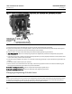
D With lever-operated switches, remove the switches as an assembly by removing the cap screws (key 75, figure 16)
and the switch mounting plate (key 1, figure 16). In order to gain access to the cap screws, it may be necessary to
loosen the hex nuts (key 77, figure 16) and slide t he switches away from the actuator housing.
WARNING
To avoid personal injury from precompressed spring force suddenly thrusting parts away from the actuator, spring
compression must first be relieved by rotating the spring adjusting screw until the spring seat is bottomed against the
spring adjuster. C losely follow the instructions below.
b. To relieve spring compression, insert a screwdriver into the notches on the spring adjusting screw and rotate the
spring adjusting screw to the right (counter-clockwise when viewed from the top of the actuator) until the spring
seat (key 13) is bottomed against the spring adjuster.
2. For 1051 and 1052 Actuators, using a 5/16 inch hex wrench, unscrew and remove the socket head cap screw (key 9)
which secures the diaphragm plate (key 4) to the diaphragm rod (key 10). Remove the diaphragm plate and the
upper thrust washer (key 83 for 1051, or key 72 for 1052).
3. For the 1051, remove the spring (key 11) and spring seat (key 14).
For the 1052, r emove the spring (key 11), spring seat with adjusting screw (keys 74 and 14), and l ower thrust washer
(key 72).
Note
At this stage of disassembly, it may be determined that further disassembly is not necessary. If separation of the diaphragm rod
from the lever is not warranted, proceed to the Assembly portion of this procedure.
4. To gain access to the cap screw (key 18) which secures the diaphragm rod to the lever, the housing cover assembly
(key 33) must be removed. Before the housing cover assembly can be removed, one of the following procedures
must be performed. Proceed as appropriate:
For actuators with valve bodies mounted on the housing cover assembly (key 33) side of the actuator, the actuator
must be separated from the valve body to provide access to the cap screw (key 18). Proceed to the Disassembly
portion of the Changing or Replacing Actuator Lever procedure and perform steps 2 through 6.
For actuators with valve bodies mounted on the actuator housing boss side of the actuator, remove the travel
indicator pointer (key 37).
5. Remove the cap screws and washers (keys 34 and 63) and the housing cover assembly (key 33).
6. Remove the outer switch cam, if used, by removing the two hex head machine screws, spacers, and retaining
washers (keys 119, 132, and 144, figures 15 and 16). Note that the retaining washers help to keep all parts together
as an assembly.
7. Remove the cap screw (key 18) that secures the actuator lever (key 27) to the diaphragm rod. Remove the
diaphragm rod.
8. Inspect all parts and replace if necessary.
9. Iftotaldisassemblyoftheactuatorisrequired,oriftheactuatorwillbeassembledforusewithavalvebodywitha
different valve shaft diameter, proceed to the Changing or Replacing Actuator Lever procedure.