
Instruction manual

1051 & 1052 F & G Actuators
Instruction Manual
Form 5062
May 2008
17
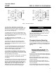
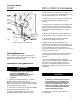
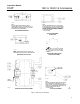
Figure 6. Actuator Locking Mechanism
MODIFIED
HOUSING
(KEY 20)
PADLOCK
(CUSTOMER
SUPPLIED)
CAP SCREW (1 REQ’D)
(KEY 129)
LEVER
34B0458-A
A6808 / IL
LEVER
CAP SCREW
GROOVE PIN
(KEY 127)
JAM NUT (KEY 128)
MOUNTING
PLATE ASSY
(KEY 124)
LOWER
LOCKING DISC
Locking Mechanism
Refer to figure 6 when installing, operating, and
locking the mechanism. Key numbers are shown in
figure 6 unless otherwise noted.
Installing the Locking Mechanism
WARNING
To avoid personal injury, perform the
steps in the WARNING at the
beginning of the Maintenance section
to isolate the control valve and
actuator.
1. To add the locking mechanism to an existing
actuator, contact your Emerson Process
Management sales office to purchase the required
parts. The required parts are the locking mechanism
and a modified actuator housing.
2. To remove the old housing, use the Disassembly
procedures in the Maintenance section.
3. Attach the mounting plate (key 123) to the
modified housing (key 20) as shown in figure 6.
Attach it with the cap screw (key 129). Make sure
the hole in the center of the mounting plate lines up
with the large tapped hole in the housing.
4. Make sure the jam nut (key 128) is threaded onto
the threaded bolt before threading it into the
housing.
5. After the bolt is threaded into the housing, install
the groove pin (key 127) into the end of the bolt.
(Note: The groove pin will prevent the threaded bolt
from being totally unthreaded from the actuator
housing.)
6. Make sure that the bolt is not threaded in so far
that it will interfere with reassembly of the actuator.
7. Reassemble actuator using the Assembly
procedure in the Maintenance section.
8. Make sure the actuator diaphragm rod is
retracted fully. This will be the locked position of the
valve. For a push-down-to-close valve and actuator,
the valve will be fully open when locked. For a
push-down-to-open valve and actuator, the valve will
be fully closed when locked.
9. Screw the threaded bolt into the housing until it
contacts the head on the lever cap screw (see
figure 6).
10. Insert the padlock (customer supplied) to
connect the mounting plate (key 123) with the lower
locking disc on the mounting plate assembly
(key 124). You might have to back off the lower
locking disc a slight amount to line up the holes for
the padlock.
CAUTION
In the larger sized actuators, the layers
of the mounting plate assembly may
be far enough apart that you will need
to purchase a padlock with a longer
loop. Do not attempt to force the layers
closer to fit a small looped padlock, as
property damage may result.
11. Tighten the jam nut (key 128) against the
mounting plate.