
Instruction manual


Instruction Manual
D100320X012
1051 and 1052 H & J Actuators
October 2012
12
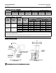
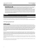
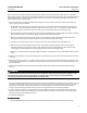
Figure 9. Center of Gravity Dimensions
ACTUATOR TYPE AC TUATOR SIZE
X Y
mm Inch mm Inch
1051
40 15 0.6 191 7.5
60 10 0.4 361 14.2
1052
40 15 0.6 241 9.5
60 10 0.4 432 17.0
70 23 0.9 488 19.2
Y
X
19A1459-B
A3255
Loading Connection
1. Connect the loading pressure piping to the pressure connection in the top of the diaphragm casing.
For size 40 through 60 actuators, run either NPS 1/4 pipe or 3/8-inch tubing between the NPT 1/4 pressure connection
and the positioner or automatic controller.
For size 70 actuators, run either pipe or tubing between the pressure connection and the positioner or automatic
controller. If necessary, remove the 1/4-inch bushing in the pressure connection to increase connection size.
2. Keepthelengthofpipeortubingasshortaspossibletoavoid transmission lag in the control signal. If an accessory
(such as a volume booster or a positioner) is used, be sure that the accessory is properly connected to the actuator.
If a positioner is part of the assembly, the pressure connection to the actuator will normally be made at the factory.
3. When the actuator is completely installed and connected to the instrument, check for correct action (air-to-open or
air-to-close) to match the controlling instrument. For successful operation, the actuator stem and operating shaft
mustmovefreelyinresponsetotheloadingpressurechangeonthediaphragm.