
Instruction manual


Instruction Manual
D100320X012
1051 and 1052 H & J Actuators
October 2012
25
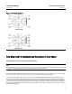
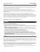
Figure 11. Travel Stop Orientation
SIZES 30 AND 40
SIZES 60 AND 70
A2534-1
Top-Mounted Handwheels and Adjustable Travel Stops
Handwheel and Travel Stop Operation
Note
If repeated or daily manual operation is expected or desired, the unit should be equipped with a manual handwheel actuator. Refer
to the separate manual handwheel actuator instruction manual for mounting instructions.
The top-mounted handwheel assembly is attached to a special upper diaphragm casing (key 1, figures 12 and 13) with
cap screws (key 141, figure 15). A hex nut (key 137, figure 15) locks the handwheel in position.
Turning the handwheel (key 51, figure 15) clockwise into the upper diaphragm casing forces the pusher (key 135,
figure 15) against the diaphragm and diaphragm plate (keys 3 and 4, figures 12 a nd 13) to compress the spring (key
11, figures 12 and 13) and move the diaphragm rod downward. Turning the handwheel counterclockwise allows the
actuator spring to move the diaphragm rod upward. If the action is push-down-to-close, full opening can be restricted
by positioning the handwheel at the desired position. If the action is push-down-to-open, full closing can be restricted
by use of the handwheel.