Instruction Manual Form 5084 Types 1098-EGR and 1098H-EGR October 2014 Types 1098-EgR and 1098H-EgR Pressure Reducing Regulators ! wARNINg Failure to follow these instructions or to properly install and maintain this equipment could result in an explosion, fire and/or chemical contamination causing property damage and personal injury or death.
Types 1098-EGR and 1098H-EGR Specifications The Specifications section lists pressure limitations and other specifications for various Types 1098-EGR and 1098H-EGR constructions.
Types 1098-EGR and 1098H-EGR Table 2. Outlet Pressure Ranges outlet pressure range psig bar 3 to 20 0.21 to 1.4 5 to 35 0.35 to 2.4 35 to 100 2.4 to 6.9 14 in. w.c. to 2 psig 35 mbar to 0.1 bar 2 to 10 0.14 to 0.69 3 to 40 0.21 to 2.8 35 to 125 2.4 to 8.6 pilot type 6351 6352 6353 spring Color Spring Part Number Green Unpainted Red Yellow Black Yellow Red 1B986027212 1B788327022 1K748527202 14A9672X012 14A9673X012 1E392527022 1K748527202 6354L(1) 85 to 200 5.9 to 13.
Types 1098-EGR and 1098H-EGR Table 5. Supply Pressure Settings Required for the Type 95H Regulator SUPPLY PRESSURE BODY SIZE NPS Type Y600AM Spring Color TYPE EGR SPRING COLOR DN Red Unpainted Yellow Green Light Blue Black psig bar psig bar psig bar psig bar psig bar psig bar 6 7 8 0.41 0.48 0.55 6 7 8 0.41 0.48 0.55 7 8 9 0.48 0.55 0.62 8 10 11 0.55 0.69 0.76 11 13 14 0.76 0.90 0.97 13 14 15 0.90 0.97 1.0 1 25 Green Blue Red 2 50 Green Blue Red 6 8 13 0.41 0.55 0.
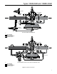
Types 1098-EGR and 1098H-EGR TYPE 6351 TYPE 1098-EGR TYPE 6352, 6353 OR 6354 Type 1098-EGR with 6350 series pilot A6563 Inlet pressure Outlet pressure ATMOSPHERIC pressure Loading pressure TYPE 1098-EGR TYPE 1806 TYPE 61LD Type 1098-EGR with type 61lD pilot and type 1806 relief valve A6641 Inlet pressure Outlet pressure ATMOSPHERIC pressure Loading pressure Figure 2.
Types 1098-EGR and 1098H-EGR TYPE 1098-EGR TYPE 95H OPTIONAL: TYPE 112 REStrictor TYPE Y600AM FIXED RESTRICTOR M1008 Type 1098-EGR with type y600AM pilot and type 95h pressure supply regulator Inlet pressure Outlet pressure ATMOSPHERIC pressure Loading pressure pilot supply pressure Figure 2.
Types 1098-EGR and 1098H-EGR control line 4 MA IN P Diameters IPE 1/2 In. / 13 mm pipe pilot supply line to pilot light (if used for boiler fuel installation) 10 M AIN PIPE DIAM ETE RS 1/2 in. / 13 mm pipe filter vent type 1098-egr or 1098h-egr regulator with standard 6350 series pilot 48A6566-A B1622 Figure 3. Standard Single-Pilot Installation 4 MA IN P IPE Diameters to pilot light PILOT SUPPLY LINE 1/2 in. / 13 mm pipe VENT 10 M AIN PIPE DIAM ETE RS 1/2 in.
Types 1098-EGR and 1098H-EGR Note Normal pressure drop assists shutoff. Therefore, leakage may result during any reverse pressure drop condition. 1. Use qualified personnel when installing, operating and maintaining regulators. Before installing, inspect the main valve, pilot and tubing for any shipment damage or foreign material that may have collected during crating and shipment. Make certain the body interior is clean and the pipelines are free of foreign material.
Types 1098-EGR and 1098H-EGR caution Introduce pilot supply pressure into the regulator before introducing any downstream pressure or internal damage may occur due to reverse pressurization of the pilot and main valve components. Always use pressure gauges to monitor downstream pressure during startup. Procedures used in putting this regulator into operation must be planned accordingly if the downstream system is pressurized by another regulator or by a manual bypass.
Types 1098-EGR and 1098H-EGR type 1098-egr size 70 with quick opening cage 20 psi / 1.4 bar maximum saftey shut-off valve gas supply to boiler fast-acting load valve type 1098-EGR type 6352 WORKING PILOT pilot gas supply type Y600AM AUXILIARY PILOT pilot gas regulator E0711 to pilot light E0710 Figure 5. Boiler Fuel Configuration Figure 6.
NLET PRESSURE Types 1098-EGR and 1098H-EGR 6350 SERIES PILOT 6350 SERIES PILOT TYPE Y600M OR 627-109 MONITORING PILOT 6350 SERIES PILOT 6350 SERIES PILOT TYPE Y600M OR 627-109 MONITORING PILOT A6788 INLET PRESSURE OUTLET PRESSURE ATMOSPHERIC PRESSURE LOADING PRESSURE INTERMEDIATE PRESSURE Figure 7. Typical Working Monitor Installation Startup OUTLET PRESSURE 1. Slowly open the pilot supply line hand valve. ATMOSPHERIC PRESSURE 2.
Types 1098-EGR and 1098H-EGR Table 6. Auxiliary Pilot Selection (Fast Stroke Dual Pilot) SIZE CONSTRUCTION Type Y600AM ORIFICE In. 1/4 SPRING RANGE psi bar SPRING NUMBER 4 to 8 in. w.c. 10 to 20 mbar 1B653827052 Red 7 to 16 in. w.c. 17 to 40 mbar 1B653927022 Unpainted 15 in. w.c. to 1.2 psi 37 mbar to 0.08 bar 1B537027052 Yellow 1.2 to 2.5 0.08 to 0.17 1B537127022 Green 2.5 to 4.5 0.17 to 0.31 1B537227022 Light Blue 4.5 to 7 0.31 to 0.48 1B537327052 Black 5 to 10 0.34 to 0.
1098-EGR Upstream or Downstream “Wide-Open” Moni URE SURE PILOT SUPPLY REGULATOR Types 1098-EGR and 1098H-EGR PILOT SUPPLY REGULATOR 6350 SERIES PILOT A6789 INLET PRESSURE C PRESSURE E PRESSURE 6350 SERIES PILOT 6350 SERIES PILOT OUTLET PRESSURE LOADING PRESSURE MONITOR LOADING PRESSURE ATMOSPHERIC PRESSURE INTERMEDIATE PRESSURE Figure 8.
Types 1098-EGR and 1098H-EGR BODy FlANgE SEAT RINg SCREwS INTO CAgE CAgE SCREwS INTO BODy FlANgE P1507 P1508 Figure 9. Trim Package Removal 3. Slowly open the hand valve in the control line and adjust the pilot setting if necessary. Set the monitoring regulator at a slightly higher control pressure than the working regulator. 4. Completely open the downstream block valve. 5. Slowly close the bypass valve, if any.
Types 1098-EGR and 1098H-EGR (key 13, Figure 14) are updated to accurately indicate any field changes in equipment, materials, service conditions or pressure settings. ! 19 10 Warning 37 To avoid personal injury resulting from sudden release of pressure, isolate the regulator from all pressure and cautiously release trapped pressure from the regulator before attempting disassembly.
Types 1098-EGR and 1098H-EGR Type EGR Main Valve Cap Screw (key 3) Torque SIZE Torque NPS DN Ft-lbs N•m 1 25 75 to 95 102 to 129 2 50 55 to 70 75 to 95 3 80 100 to 130 136 to 176 4 100 160 to 200 217 to 271 6, 8 x 6, 12 x 6 150, 200 x 150, 300 x 150 275 to 300 373 to 407 1. Remove the travel indicator assembly by removing lower indicator fitting (key 5) from the body flange (key 2). 2.
Types 1098-EGR and 1098H-EGR cage. Apply a thin coating of lubricant to seals for protection during assembly. Use the valve body (key 1) as a holding fixture during this step as shown in Figure 10 and insert a wrench handle (or similar tool) into the seat ring slots for leverage when tightening the seat ring and cage. 8. Remove the upside-down body flange (key 2) if it was anchored on the body.
Types 1098-EGR and 1098H-EGR manufactured before May 1999 need to have the body plug gasket and the body plug replaced with a new body plug assembly (key 3), which includes the body plug and the body plug O-ring. Install the body plug O-ring over the body plug. Stack the valve spring and the inner valve assembly on the body plug assembly (key 3) and install the body plug assembly with stacked parts into the body.
Types 1098-EGR and 1098H-EGR a. Before replacing the diaphragm case (key 2) or spring case (key 1), be sure the yoke assembly is positioned so that it will not bind or rub on the prong in the relay body. b. Avoid wrinkling the diaphragms (key 14 and 15) when replacing the diaphragm case (key 2) and spring case (key 1). c. Replace the diaphragm case (key 2), carefully working the upper relay diaphragm (key 14) into the recess in the diaphragm case.
Types 1098-EGR and 1098H-EGR 4. To replace the lever assembly (key 16), remove the machine screws (key 17). To replace the stem (key 14) or stem O-ring (key 30), also perform Body Area Maintenance procedure steps 1 and 4 and pull the stem (key 14) out of the diaphragm casing (key 4). Grease the replacement stem O-ring (key 30) with a good grade of lubricant and install it on the stem (key 14). 5.
Types 1098-EGR and 1098H-EGR Types 1098 and 1098H Actuator and Pilot Mounting Parts Perform this procedure if changing the actuator or inspecting, cleaning or replacing actuator and/or pilot mounting parts. Actuator part key numbers are referenced in Figure 14 and mounting part numbers in Figure 27, unless otherwise indicated. 1. The actuator and pilot(s) may be removed and replaced as a unit by disconnecting the control line and pilot supply line. 2.
Types 1098-EGR and 1098H-EGR Parts List (continued) Type EGR Main Valve (Figures 12 and 13) Key Description Elastomer Trim Parts kit (included are: keys 4, 7, 12, 14, 15, 17, 20, 21, 36 and 37) Nitrile (NBR) NPS 1 / DN 25 NPS 2 / DN 50 NPS 3 / DN 80 NPS 4 / DN 100 NPS 6 / DN 150 Fluorocarbon (FKM) NPS 1 / DN 25 NPS 2 / DN 50 NPS 3 / DN 80 NPS 4 / DN 100 NPS 6 / DN 150 Ethylenepropylene (EPR) NPS 1 / DN 25 NPS 2
Types 1098-EGR and 1098H-EGR Key 1, Type EGR Main Valve Bodies Material End Connection NPS 1 / DN 25 nps 2 / DN 50 NPT 34B7611X012 38A8845X012 CL125 FF 34B8630X012 38A8847X012 Cast Iron WCC Steel CF8M Stainless steel / NACE NACE WCC Steel CL250 RF 37B5950X012 38A8846X012 NPT 37B5946X012 38A8848X012 CL150 RF 37B5947X012 38A8853X012 CL300 RF 37B5948X012 38A8849X012 CL600 RF 37B5949X012 38A8844X012 SWE GE05951X012 GE05958X012 SCH 40 BWE GE05953X012 GE05957X012 SCH 80 BWE GE0
Types 1098-EGR and 1098H-EGR Type EGR Main Valve (Figures 12 and 13) (continued) Key Description Part Number 3 Stud Bolt, Stainless steel (use with Stainless steel body) (not shown) NPS 1 / DN 25 (4 required) 1R284835222 NPS 2 / DN 50 (8 required) 1K242935222 NPS 3 / DN 80 (8 required) 1A378135222 NPS 4 / DN 100 (8 required) 1R369035222 NPS 6, 8 x 6 or 12 x 6 / DN 150, 200 x 150 or 300 x 150 (12 required) 1A365635222 4*(1) Gasket, composition NPS 1 / DN 25
Types 1098-EGR and 1098H-EGR 21 27 INDICATOR PLUG ASSEMBLY 19 18 10 37 22 7 8 21 35 6 5 3 36 2 31 24 4 26 20 14 23 15 28 9 11 17 16 13 1 12 24 25 35A3167 COMPLETE CAST IRON FULL-CAPACITY MAIN VALVE ASSEMBLY Figure 12.
Types 1098-EGR and 1098H-EGR 19 18 10 22 35 8 37 36 7 5 21 31 6 2 14 4 15 20 9 23 11 28 12 17 16 13 32 28 26A3800 Detail of optional restricted Capacity construction Quick-Change Trim Package Assembly 25A3170 Figure 13.
Types 1098-EGR and 1098H-EGR Type EGR Main Valve (Figures 12 and 13) (continued) Key Description 15* Upper Seal Nitrile (NBR)(1) (standard) NPS 1 / DN 25 NPS 2 / DN 50 NPS 3 / DN 80 NPS 4 / DN 100 NPS 6, 8 x 6 or 12 x 6 / DN 150, 200 x 150 or 300 x 150 Fluorocarbon (FKM) NPS 1 / DN 25 NPS 2 / DN 50 NPS 3 / DN 80 NPS 4 / DN 100 NPS 6, 8 x 6 or 12 x 6 / DN 150, 200 x 150 or 300 x 150 Ethylenepropylene (EPR)
Types 1098-EGR and 1098H-EGR Type EGR Main Valve (Figures 12 and 13) (continued) Key Description 27 Indicator Plug Zinc-plated steel NPS 1 / DN 25 NPS 2 / DN 50 NPS 3 / DN 80 NPS 4 / DN 100 316 Stainless steel (NACE) NPS 1 / DN 25 NPS 2 / DN 50 NPS 3 / DN 80 NPS 4 / DN 100 NPS 6, 8 x 6 or 12 x 6 / DN 150, 200 x 150 or 300 x 150 28 Spring Seat Full capacity trim(1) Plated steel NPS 1 / DN 25 NPS 2, 3 or 4 / DN 50, 80 or
Types 1098-EGR and 1098H-EGR 6 8 28 3 56 12 57 5 27 2 6 56 57 56 6 13 7 4 9 1 11 10 34A5692 Type 1098 28 6 29 36A8540 13 57 12 9 1 56 7 2 27 11 8 10 Type 1098H Figure 14.
Types 1098-EGR and 1098H-EGR Types 1098 and 1098H Actuators (Figure 14) (continued) Key Description 7 Diaphragm (continued) Type 1098H Ethylenepropylene (EPDM) Size 30 Size 40 Size 70 Nitrile (NBR) Fluorocarbon (FKM) Ethylenepropylene (EPDM) 8 Diaphragm Plate Size 30 Cast Iron 316 Stainless steel (NACE) Size 40 Cast Iron 316 Stainless steel (NACE) Size 70 Cast Iron WCC Steel (NACE) 316 Stainless steel (NACE) 9
Types 1098-EGR and 1098H-EGR 6 5 2 5 7 1 4 3 AJ5004 Figure 15. Standard P590 Series Filter Assembly 12 11 8 35 1 24 4 S 34A5853 28 10 2 9 7 22 6 3 42 APPly SEAlANT (S) S = MulTI-PuRPOSE PTFE THREAD SEAlANT Figure 16.
Types 1098-EGR and 1098H-EGR Type 6351 Pilot (Figure 16) (continued) Key Description 7* Diaphragm Assembly (includes plated steel diaphragm plate) Nitrile (NBR) diaphragm and Aluminum pusher post Nitrile (NBR) diaphragm and Stainless steel pusher post Fluorocarbon (FKM) diaphragm and Aluminum pusher post 8 Upper Spring Seat 9 Control Spring, plated steel 3 to 20 psig / 0.21 to 1.4 bar range, Green 5 to 35 psig / 0.35 to 2.
Types 1098-EGR and 1098H-EGR 11 2 14 15 10 7 9 20 6 5 22 8 1 23 4 13 16 3 19 35A8889 21 12 17 35A6236 Detail of Type 6354M or 6354H pilot Type 6352, 6353 or 6354L pilot Figure 17.
Types 1098-EGR and 1098H-EGR Types 6352, 6353, 6354L, 6354M and 6354H Pilots (Figure 17) (continued) Key Description 14 Machine Screw (6 required) Aluminum Stainless steel 15 Relief Valve Assembly 25 psig / 1.7 bar 25 psig / 1.7 bar (NACE) 25 psig / 1.7 bar (for Oxygen service) 25 psig / 1.
Types 1098-EGR and 1098H-EGR 30 3 26 10 13 11 14 16 25 5 4 24 20 2 12 9 15 50 1 27 35 6 41 17 7 19 35 34 23 6 S 8 18 34 28 30A6330 32A2068 Detail of Capped Adjusting Screw OPTION Type 61H pilot apply Sealant (S) S = multi-purpose ptfe thread sealant Figure 19. Type 61H Pilot Assembly 6 34 7 35 50 1 27 48 16 42 14 10 4 45 26 13 47 2 15 52 51 53 3 19 34A0396 46 Figure 20.
Types 1098-EGR and 1098H-EGR 61 Series Pilots (Figures 18, 19 and 20) (continued) Key Description Part Number 10 Bleed Orifice, 303 Stainless steel Types 61L, 61LD, 61LE and 61H Standard bleed 1B887335032 Special bleed 1C831435032 Capped bleed (for Types 61L and 61LD only) 1D777135032 Type 61HP 1D318135032 11 Diaphragm Nut, (for 61 Series except Type 61HP) Standard trim, Oxygen service and pressure loaded trim for corrosive service, 316 Stainless steel 1B98
Types 1098-EGR and 1098H-EGR 3 4 8 16 17 18 L1 L1 14 31 11 48 1 36 38 22 35 10 12 33 13 5 26 50 6 25 L2 7 24 30 15 L1 L1 2 L2 47B3687 47B3687 apply lubricant (l) l1 = silicone grease lubricant l2 = anti-seize and lubricating compound Figure 21. Type Y600AM Regulator Assembly Figure 22.
Types 1098-EGR and 1098H-EGR l2 l2 15 l2 17 11 9 8 12 16 2 7 1 3 6 4 30A7022 10 5 l2 APPly ANTI-SEIzE COMPOuND (l2) Figure 23.
Types 1098-EGR and 1098H-EGR 26 23 control line connection bottom view of pilot (shown rotated 90° from normal) 24 25 14A5706-A Figure 24. Single-Pilot Mounting Assembly Mounting Parts 6350 Series Mounting Parts (Figure 24) Key Description 16 Pipe Tee for use with 50 psig / 3.4 bar relief 21 Tube Fitting Connector for use with 50 psig / 3.
Types 1098-EGR and 1098H-EGR 15 14 16 control line connection FISHER 22 14A5705 20 19 18 21 17 Figure 25.
Types 1098-EGR and 1098H-EGR 36 32 22 30 24 31 34 35 37A0565 Figure 26.
Types 1098-EGR and 1098H-EGR 43 31 35 38 TyPE 95H SuPPly PRESSuRE REgulATOR 44 16 53 52 22 39 50 36 51 30 24 32 TyPE y600AM PIlOT 42B6644 52 OPTIONAl: TyPE 112 RESTRICTOR Figure 27.
Types 1098-EGR and 1098H-EGR 24 B 44 B VIEW A-A 45 VIEW B-B 16 37 48 S SUPPLY 21 43 6350 SERIES type y600am A 41 VENT 39 A 47 CONTROL 38 47A7118 Type Y600AM and Size 70 type 1098 Combination B 44 S B SUPPLY VIEW A-A 45 VIEW B-B 32 type 621-107 37 48 30 6350 SERIES 31 A 21 41 A 47A7119 24 39 43 16 38 47 CONTROL Type 627M and Size 70 type 1098 Combination apply sealant (s) all npt thread Figure 28.
Types 1098-EGR and 1098H-EGR Industrial Regulators Natural Gas Technologies TESCOM Emerson Process Management Regulator Technologies, Inc. Emerson Process Management Regulator Technologies, Inc. Emerson Process Management Tescom Corporation USA - Headquarters McKinney, Texas 75070 USA Tel: +1 800 558 5853 Outside U.S. +1 972 548 3574 USA - Headquarters McKinney, Texas 75070 USA Tel: +1 800 558 5853 Outside U.S.