
Data Sheet

23
Two-Stage Systems
Regulator Technologies Fisher
®
brand makes the LP-Gas industry’s
largest variety of First and Second-Stage regulators for domestic
and commercial/industrial applications.
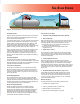
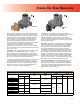
A Two-Stage system (Figure 1) uses two regulators to cut the supply
pressure from the storage tank to the appliance. The Two-Stage
system supplies a constant outlet pressure to the appliance. With
more uniform pressure, appliances work better. Single-Stage
regulators should be replaced with Two-Stage or Integral Two-Stage
systems to comply with code requirements such as NFPA 58.
With a Two-Stage system, a First-Stage regulator supplies a nearly
constant inlet pressure around 8 to 10 psig / 0.55 to 0.69 bar to
a Second-Stage regulator. This means the Second-Stage unit
does not have to attempt to compensate for widely varying inlet
pressures. Second-Stage pressure can be adjusted at the building
as desired.
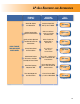
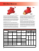
First-Stage Regulators
First-Stage regulators reduce tank pressure to a lower pressure
(usually 10 psig / 0.69 bar) for a Second-Stage regulator. Fisher brand
First-Stageregulatorsarepaintedredforeasyidentication.Ventsare
screened with standard orientation over the outlet.
Two-psi Service Regulators
Two-psi Service regulators serve as an intermediate regulator
after the First-Stage regulator. These regulators are designed for
2 psig / 0.14 bar LP-Gas regulator systems. Fisher brand 2-psi
regulators are painted white or are green with white closing caps
foreasyidentication.
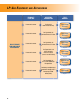
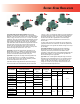
Second-Stage Regulators
Second-Stage regulators reduce the pressure from a First-Stage
unit to 11 inches w.c. / 27 mbar in domestic installations. Vents are
screened with standard orientation over the inlet; however, other vent
orientations are available. Fisher brand Second-Stage regulators are
normallypaintedpalmgreenforeasyidentication.
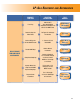
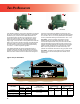
Integral Two-Stage Regulators
Integral Two-Stage units combine a First-Stage regulator
and Second-Stage regulator into one compact unit and are
recommended for installations where piping distance between the
building being served and the tank is short. Integral Two-Stage
regulators provide all the advantages of Two-Stage regulation.
Theseunitsarecolorcodedgrayforeasyidentication.Ventsare
screened with standard orientation over the outlet.
Five Reasons to Two-Stage
1. Compliance with Code Requirements such as NFPA 58
2. Fewer Trouble Calls
With a Two-Stage system, one can expect fewer customer trouble
calls due to regulator freeze-ups from too much water in the gas. A
Two-Stage regulator reduces these possibilities in two ways:
a)alargeroricecanbeused,makingitmoredifcultforice
tobuildupandblocktheorice,and
b) more heat can be transferred through the walls of two
regulators than one
3. Smaller Pipe or Tubing
Due to the higher pressure between the First and Second-Stage
units, smaller pipe or tubing can be used on a Two-Stage system.
These savings can make a Two-Stage system more economical to
install than a Single-Stage.
4. Constant Appliance Pressure
With a Two-Stage system, a First-Stage regulator supplies a
nearly constant inlet pressure of 8 to 10 psig / 0.55 bar to 0.69 bar
to a Second-Stage regulator. This means that the Second-Stage
regulator does not have to attempt to compensate for widely varying
inlet pressures. With more uniform pressure, appliances work better
and customers are less likely to experience problems that result in
service calls.
5. Keep Downstream Pressure Below 2 psig / 0.14 bar
Second-Stage and Integral Two-Stage regulators have internal
pressure relief valves, which limit the outlet pressure to 2 psig /
0.14 bar when the seat disc is removed and the inlet pressure
is10psig/0.69barorlessasspeciedinUL 144, STANDARD
FOR LP-GAS REGULATORS.
When to Two-Stage
Two-Stage systems whenever the following conditions exist:
1. Compliance with regulation codes.
2. There is a possibility of moisture in the LP-Gas.
3.Wideuctuationsingasdemandexist.
4. Winter and summer temperatures vary greatly.
FIRST–STAGE REGULATOR
USUALLY 10 psig /
0.69 bar
SECOND–STAGE REGULATOR
11 INCHES W.C. / 27 mbar
Figure 1. Two-Stage Regulation, One at Tank and One at Building, Reduce Pressure Down to Burner Pressure (11 inches w.c. / 27 mbar)
TWo-sTage sYsTeM