
Instruction manual


168, 168H, and 68 Series
D100275X012
Instruction Manual
Form 2256
December 2008
www.emersonprocess.com/regulators
168, 168H, and 68 Series Three-Way
Switching Valves
Introduction
The 168 and 168H Series pneumatically operated
three-way snap-acting switching valves (Figure 1) are
used to switch pressures on and off in response to a
predetermined change in an input signal pressure.
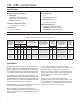
In operation, increasing pressure applied to the top of
the diaphragm through port D (see Figure 2) moves
the stem and upper range adjusting nut toward the
trip lever. When the diaphragm pressure reaches
the predetermined upper tripping pressure, the upper
adjusting nut pivots the trip lever to move the rocker
assembly to its alternate position, closing port C
and opening port B. When decreasing pressure to
the diaphragm at port D reaches the lower tripping
pressure, the spring moves the stem and lower range
adjusting nut to return the rocker to its original position,
closing port B and opening port C.
The 68 Series (Figure 4) three-way snap-acting body
assemblies can be used alone, or to form the valve
body portions of 168 or 168H Series switching valves.
With the addition of the lever knob (key 11, Figure 4)
to a Type 68-1 body assembly, a Type 68-2 manual
switching valve body assembly is formed.
Only personnel qualied through training or experience
should install, operate, and maintain these valves. If
there are any questions concerning these instructions,
contact your local Sales Ofce before proceeding.
W1932
Figure 1. Exterior of 168 Series Switching Valve
Figure 2. Construction Details of
168 Series Switching Valve
DIAPHRAGM
DIAPHRAGM
SPRING
ROCKER
ASSEMBLY
B
A
C
BODY
BODY SPRING
TRIP LEVER
LOWER RANGE
ADJUSTMENT NUT
STEM
UPPER RANGE
ADJUSTMENT NUT
D
M1045
INLET PRESSURE
OUTLET PRESSURE
ATMOSPHERIC PRESSURE
LOADING PRESSURE