
Air Cleaner User Manual


12
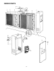
POWER SUPPLY
CHECKOUT PROCEDURE
1. Turn power switch to the “OFF” position and remove
the power pack from cabinet.
2. Place power pack on a well insulated workbench.
Connect meter negative (-) lead to the sheet metal
chassis and the high voltage probe to high voltage
contact on back cover of power pack. Connect AC
power to power pack using an extension cord and
turn power switch to the “ON” position. Keep hands
and tools away from high voltage contact.
3. If Operating Light comes ON and output voltage is
between 6100 and 6800 VDC, power supply is good.
4. If voltage is good but Operating Light does not come
on, replace Operating Light.
CELL TEST
1. Place collecting cell on a well insulated workbench
with the cell contact button pointing upward.
2. Select a power pack (with ozone reduction jumper
intact) that reads between 6100 and 6800 VDC at the
cell contact with no cell attached.
3. Place power pack on top of collecting cell ensuring
that there is proper contact between the cell contact
on the power pack contact.
4. Using a standard extension cord, apply 120 VAC to
power pack. Turn power switch to “ON” position.
5. Connect meter negative (-) lead to metal frame of
collecting cell. Use high voltage probe to measure
voltage at collecting cell ionizer or cell plates. Voltage
should be 6100 to 6800 VDC**.
NOTE: A new “out-of-box” cell may cause the voltage
to be lower than normal for a short period of time. To
obtain a more accurate measurement, “age” the cell
by applying high voltage to the cell for 15 to 30
minutes.
6 If voltage is below 6100 VDC, check cell for foreign
objects, bowed/bent/loose plates, broken ionizing
wires or cracked insulators. Wash cells if required. If
Operating Light remains OFF, replace collecting cell.
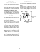
LINE
WHT/BRN BLK
W1
E3 E2
Ozone Reduction Jumper
Cut and separate
Ozone Reduction
Jumper
Figure 24
OZONE REDUCTION
All electronic air cleaners typically produce a small amount
of ozone that is within established limits. Some customers
may notice an odor especially at high altitudes or low air
flow rates.
This power supply has a “hairpin” shaped jumper wire
labeled W1 (see Fig 24) that can be cut and separated in
case of such complaints. This will cause the power supply
to limit the maximum operating power to a lower level.