
Thermostat User Manual

1A11-2 LIGHT DUTY FAN COIL THERMOSTAT
For Direct Control of Line Voltage Valves and/or Blower Motors on
Fan Coil Units Featuring Manual Changeover From Heat to Cool and
a 3-Speed Fan Switch, Subbase Included
FEATURES
•Mountstoastandardverticaloutletboxoronatwo-gangoutletbox.Mayalsobe
mounted on a 4” x 4”junctionboxwithanadapter(notprovided).
•Wiringcolorcodedforeaseofinstallation.
•3-speedmanualfanswitch:High–Medium–Low.
•SystemSwitch:Heat–OFF–Cool.“OFF”breaksbothvalveandfancircuits.
•Beigecolor.
1A11-2
– Thermostat cycles both fan and valve
– Thermostat cycles fan only (if valve is not used tape orange lead)
–System“OFF”breaksbothvalveandfancircuits
– Thermostat cycles valve only with continuous fan (interchange valve and L1 leads)
SPECIFICATIONS
Dimensions........................ 4
1
/
2
”H x 4
1
/
2
” W x 2
1
/
4
”D
Agency . . . . . . . . . . . . . . . . . . . . . . . . . . . U.L. listed and C.S.A. approved
PARTS AND ACCESSORIES
•Thermostatguards–seepages24-25
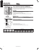
LINE VOLTAGE
THERMOSTATS
TAN
BLUE
COOL
COOL
HEAT
HEAT
VALVE
(SOL)
L1*
(HOT)
GNDHIGH
HIGH
FAN
SWITCH
SYSTEM
SWITCH
MED
FAN
MED
OFF
LOW
LOW
RED
BLUE
RED
ORANGE
BLACK
GREEN
1A11-2
5-wire with ground, for single valve,
manual heat/cool changeover
CUSTOMER
CONNECTIONS
Note: Above FAN and SYSTEM switches shown in
MED and HEAT positions respectively.
THERMOSTAT
SCHEMATIC
*L1 is Power In
Model
Number Range Differential
Switch
Action
Contact Ratings Pilot Duty
Motor Ratings (inductive) Full Load Motor Ratings (inductive) Locked Rotor 120/240
120 VAC 240 VAC 277 VAC 120 VAC 240 VAC 277 VAC 277 VAC
1A11-2 36 to 90°F
(2 to 32°C)
1.5°F SPDT 5.5A 2.75A 2.3A 33.0A 16.5A 13.8A 120A
THERMOSTATS
www.white-rodgers.com
30