
Specifications


F145-1328/F145-1378
Indoor Remote Sensor/Outdoor Remote Sensor
INSTALLATION INSTRUCTIONS
FAILURE TO READ AND FOLLOW ALL INSTRUCTIONS CAREFULLY
BEFORE INSTALLING OR OPERATING THIS CONTROL COULD CAUSE
PERSONAL INJURY AND/OR PROPERTY DAMAGE.
SPECIFICATIONS
CAUTION
!
To prevent electrical shock and/or equipment
damage, disconnect electric power to system
at main fuse or circuit breaker box until instal-
lation is complete.
WARNING
!
Do not use on circuits exceeding specied
voltage. Higher voltage will damage control
and could cause shock or re hazard.
Do not short out terminals on gas valve or prima-
ry control to test. Short or incorrect wiring will
damage thermostat and could cause personal
injury and/or property damage.
For applications where the wire run is short (100 ft.
or less) shielded cable may not be required provided
the wires are not routed parallel to or across other
wires carrying electrical power. To reduce electrical
interference or inductance from other electrical wir-
ing or devices use shielded cable and keep Remote
Sensor wire runs separate from thermostat wiring.
Remote sensors cannot be used with systems where
power interruptions are part of normal system op-
eration. Compatible with all White-Rodgers remote
sensing thermostats.
Operating Range: (based on thermostat range)
F145-1328 Indoor Model: 40 to 99°F
F145-1378 Outdoor Model: -40 to 140°F
Operating Humidity Range: 0 to 90% RH
(non-condensing)
Maximum Distance from Thermostat: 300 feet
Recommended Wire: 18 or 20 gauge,
3-conductor shielded cable
Color: Classic White
Dimension: 2 1/8" x 3 1/2" x 3/4"
Outdoor Remote includes 12 ft. of outdoor
probe lead
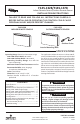
F145-1328
INDOOR REMOTE SENSOR
F145-1378
OUTDOOR REMOTE SENSOR
Interior Mounting Base
Outdoor Probe
CONTENTS
Specications ................................................ 1
Installation .................................................... 2
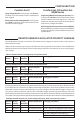
Remote Sensor Terminal Cross Reference ...... 2
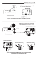
Wiring F145-1328 (Single Stage) ..................... 3
Wiring F145-1328, F145-1378 (Mul-Stage) ... 3
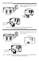
Wiring 1F97-1277 (Blue Touchscreen) .............4
Wiring 1F95-1277 (Blue Touchscreen) ............ 4
Conguration .................................................5
Remote Sensor Calculated Priority Average .....5
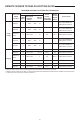
Maximum Sensing Locaons
Per Thermostat (Chart) ..................................6
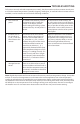
Troubleshoong ...............................................7
PART NO. 37-6606C
Replaces 37-6606B
1319
www.white-rodgers.com
www.emersonclimate.com