
Specifications


2
INSTALLATION
INDOOR SENSOR
SELECT SENSOR LOCATION
Proper location insures that the remote sensor will
provide a comfortable home or building tempera-
ture. Observe the following general rules when
selecting a location:
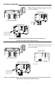
1. The remote sensor can be located a maximum
of 300 feet from the thermostat.
2. Locate sensor about 5 . above the room oor
level.
3. Install sensor on a partitioning wall, not on an
outside wall.
4. Never expose sensor to direct light from lamps,
sun, replaces or any temperature radiating
equipment.
5. Avoid locations close to windows, adjoining
outside walls, or doors that lead outside.
6. Avoid locations close to air registers or in the
direct path of air from them.
7. Make sure there are no pipes or duct work in that
part of the wall chosen for the sensor location.
8. Never locate sensor in a room that is normally
warmer or cooler than the rest of the home
(such as the kitchen) or building.
9. Avoid locations with poor air circulation, such
as behind doors or in alcoves.
10. In the home, the living or dining room is normally
a good location, provided there is no cooking
range or refrigerator on opposite side of wall.
OUTDOOR SENSOR
SELECT SENSOR LOCATION
Proper location insures that the remote sensor will
provide a correct outdoor temperature reading.
Observe the following general rules when selecting
a location:
1. The interior mounting base can be located a
maximum of 300 feet from the thermostat.
2. Install the interior mounting base within 12 .
of the intended outdoor probe location.
3. Never install the outdoor probe where it will be
exposed to direct light from lamps, sun, re-
places or any temperature radiating equipment.
4. Make sure there are no pipes or ductwork in the
wall chosen for the base location.
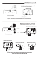
5. Outdoor temperature measurement requires
installing the probe outdoors. Good probe loca-
tions would be under a bay window or overhang,
out of direct sunlight. Direct sun exposure will
aect sensed temperature. Install probe with
spacer to obtain a more accurate temperature.
Mounting
Surface
Spacer
6. Although connected to the probe wire for out-
door temperature sensing, the interior mount-
ing base must be placed indoors. Therefore, the
interior mounting base must be installed near
the perimeter of the building, so that the probe
wire can be run through to the outside of the
structure and placed in the selected (shaded)
location. The outdoor probe wire is 12 feet
long (and should not be cut or spliced), so plan
the placement of both the probe and interior
mounting base accordingly. Any excess wire
may be coiled or bundled. The probe should be
connected to E2 as shown in gure 2.
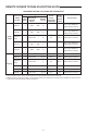
REMOTE SENSOR TERMINAL CROSS REFERENCE
Old/New Remote Terminal Designations
Model Number Terminal Designation
*F145-1049,
*F145-1170
S1 S2 S3
F145-1328,
F145-1378
+ S -
Sensor
Positive
Sensor
Return
Signal
Sensor
Negative
*Models no longer available
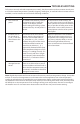
CAUTION
!
Do not allow the 3-conductor wire to be pinched
between the sensor and the wall.
Check wire connections before applying power.
Improper connections will lead to permanent
damage to the sensor.
When shielded cable is used, cable shield
must be connected to "-" or S3 on the
THERMOSTAT ONLY.