Operating Manual 24685034, Rev. AE June 2011 Hydrastep 2468CB and 2468CD Electronic Gauging System (Dual Power Supply Version) www.mobrey.
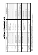
Hydrastep system does not power-up. Chequered / intermittent display. No display. Yellow LED illuminated. Chequered / intermittent display. No display. Yellow LED illuminated. Flashing Red (steam) and Green (water) LED’s with Yellow alarm LED illuminated.
Ensure wiring is of the correct type and that the wiring diagram supplied has been followed. Hydrastep relies on a ‘path back to earth’. Please make sure that all earth points are made and are of a good standard. Great care must be taken with the mounting of the water column; the columns must be vertical; angles stated in the manual should be as close as possible, as this ensures condensate flow back into the column. Lagging of the pipe work must be as stated; ** The last 0.
About this manual This manual describes the Hydrastep 2468CB and 2468CD Electronic Gauging Systems along with the recommended options. Except where stated otherwise, the information contained in this manual can be assumed to apply to either system. This manual is divided into three parts; the first covers the electrical/electronic system; the second describes the pressure parts; the third is for coverage of all other aspects.
SYMBOLS USED IN THIS MANUAL AND ON THE UNIT Symbol Meaning Direct Current Alternating Current Earth (ground) terminal Protective conductor terminal Caution (refer to accompanying documents)
Part 1 Hydrastep 2468CB & 2468CD Electronic Gauging System 24685034 Pt.
Pt.
DANGEROUS VOLTAGES ARE PRESENT IN THIS EQUIPMENT. ANY WARNING NOTICES OR PROCEDURES CONTAINED IN THIS MANUAL OR ON THE EQUIPMENT SHOULD BE STRICTLY OBSERVED TO MAINTAIN SAFETY. THE USE OF THIS EQUIPMENT IN A MANNER NOT SPECIFIED IN THIS MANUAL MAY IMPAIR THE PROTECTION PROVIDED BY THIS EQUIPMENT. GREAT CARE SHOULD BE EXERCISED WHEN SERVICING THIS EQUIPMENT.
Pt.
Part 1 Contents 24685034 Chapter 1 Introduction to the Hydrastep 2468 Electronic Gauging System Chapter 2 2468CB & 2468CD Dual Power Supply Version Chapter 3a 2468 - Relay Output Board Option Chapter 3b Delay Relay Output Board Option Chapter 3c 2468 Opto-isolated Output Board Option Chapter 4 Remote Display Options 24683B C & D Pt.
Pt.
Hydrastep 2468CB and 2468CD Manual Introduction to the Hydrastep 2468 Electronic Gauging System 1 Introduction to the Hydrastep 2468 Electronic Gauging System Contents Page No. 1.1 WATER LEVEL MEASUREMENT .......................................................... 3 1.2 HYDRASTEP 2468 ELECTRONIC GAUGING SYSTEM ....................... 5 1.2.1 1.2.2 1.2.3 1.3 SYSTEM OPTIONS ................................................................................. 6 1.3.1 1.3.2 1.3.3 1.4 INPUT BOARDS ..........
Introduction to the Hydrastep 2468 Electronic Gauging System Hydrastep 2468CB and 2468CD Manual 0040 Figure 1.
Hydrastep 2468CB and 2468CD Manual 1.1 Introduction to the Hydrastep 2468 Electronic Gauging System WATER LEVEL MEASUREMENT The Hydrastep 2468 Electronic Gauging System is designed as an electronic alternative to water level gauges on boilers, giving a more reliable and safer water level indication than conventional visual gauges. It uses the significant difference in resistivities of water and steam in temperatures up to 370C (698F) to determine the water level. Figure 1.
Introduction to the Hydrastep 2468 Electronic Gauging System Hydrastep 2468CB and 2468CD Manual Figure 1.
Hydrastep 2468CB and 2468CD Manual 1.2 Introduction to the Hydrastep 2468 Electronic Gauging System HYDRASTEP 2468 ELECTRONIC GAUGING SYSTEM The Hydrastep 2468 is a sophisticated and flexible electronic gauging system.
Introduction to the Hydrastep 2468 Electronic Gauging System 1.2.3 Hydrastep 2468CB and 2468CD Manual SYSTEM FAULTS (2468CB OR 2468CD) System fault indication, a yellow LED and an opto-isolated output, is provided for a ‘water above steam’ condition, an electrode fault or wiring failure and the detection of an internal fault. A further fault is indicated when the electrode number switch is incorrectly set. This fault is indicated by a chequered display of red and green LEDs on the level display.
Hydrastep 2468CB and 2468CD Manual 1.4 Introduction to the Hydrastep 2468 Electronic Gauging System HYDRASTEP 2468 UPGRADE PATHS AND AVAILABLE OPTIONS Table 1.1 describes the available versions of the Hydrastep 2468 Electronic Gauging System and their possible options. Existing System Available Options Description 2468 CA or 2468 CC 16 point EGS with local display Single power supply. 2468 CB or 2468 CD 32 point EGS with local display Comments Part No.
Introduction to the Hydrastep 2468 Electronic Gauging System 1-8 Hydrastep 2468CB and 2468CD Manual 24685034
Hydrastep 2468CB and 2468CD Manual 2468CB & 2468CD Dual Power Supply Version 2 2468CB & 2468CD Dual Power Supply Version Contents Page No. 2.1 INTRODUCTION ....................................................................................... 2-3 2.2 ELECTRODE CABLING SYSTEM ........................................................... 2-3 2.3 ELECTRONIC ENCLOSURE .................................................................... 2-3 2.3.1 2.3.2 2.3.3 2.3.4 2.4 INSTALLATION ......................
2468CB & 2468CD Dual Power Supply Version 2.5.2 2.6 DISPLAY BOARD 24680515 ............................................................... 2-20 2.5.2.1 Link LK1 Setting .................................................................... 2-20 2.5.2.2 Configuring the ‘Number of Electrodes’ Switch .................... 2-20 2.5.2.3 ‘Switching Threshold’ Setting ................................................ 2-22 2.5.2.4 ‘Compatibility’ Setting ............................................................
Hydrastep 2468CB and 2468CD Manual 2.1 2468CB & 2468CD Dual Power Supply Version INTRODUCTION This chapter introduces the dual power supply version of the Hydrastep 2468 Electronic Gauging System, its mechanical installation, system configuration, simple fault analysis/corrective action capability and its specification. 2.2 ELECTRODE CABLING SYSTEM This system can have 8, 10, 12, 14, 16, 18, 20, 22, 24, 26, 28, 30 or 32 electrodes and uses 18-core electrode cables.
68CB & 2468CD Dual Power Supply Version Hydrastep 2468CB and 2468CD Manual Figure 2.
Hydrastep 2468CB and 2468CD Manual 2.3.1 2468CB & 2468CD Dual Power Supply Version INPUT BOARD (PCB 24680501 AND PCB 24680516) The input board processes the electrode inputs to provide water level data for display purposes and a current output representing the water level. Fault detection is also carried out where the condition of the electrode inputs are examined and a FAULT is indicated when: 1. An open circuit in either of the electrode conductor cores is present. 2.
2468CB & 2468CD Dual Power Supply Version 2.3.3 Hydrastep 2468CB and 2468CD Manual DISPLAY BOARD (PCB 24680515) The display board receives its power supplies and electrode data from the input boards. This data is decoded and used to illuminate the required LEDs mounted on the display board. The data is also converted to serial format for transmission to remote display units.
Hydrastep 2468CB and 2468CD Manual 2.3.3.2 2468CB & 2468CD Dual Power Supply Version Links LK2, LK3, LK4 and LK5 These links are used to select either the 8 - 16 display mode (two LEDs per electrode) or the 18 - 32 display mode (one LED per electrode). Two link headers are provided with the unit and must be fitted in either LK2 and LK4, to enable the 8 - 16 electrode mode, or LK3 and LK5, to enable the 18 - 32 electrode mode. No.
2468CB & 2468CD Dual Power Supply Version 2.4 Hydrastep 2468CB and 2468CD Manual INSTALLATION This section deals with the mechanical installation of the electronic enclosure and the electrical connections required for the basic system. Any installation dealing with the options available for use on this version of the system are covered in Chapters 3 & 4. Notes: 1. The Electronic Enclosure cover should not be removed or opened until the equipment is ready for physical installation to its fixing point.
Hydrastep 2468CB and 2468CD Manual 2468CB & 2468CD Dual Power Supply Version Figure 2.
2468CB & 2468CD Dual Power Supply Version 2.4.2 Hydrastep 2468CB and 2468CD Manual ELECTRICAL INSTALLATION This section deals with the interconnection between the electrodes and the electronic enclosure, the connection of the ac mains power supply to the electronic enclosure and the analogue output connections from the electronic enclosure. 2.4.2.
Hydrastep 2468CB and 2468CD Manual 2.4.2.2 2468CB & 2468CD Dual Power Supply Version Connecting Cables to Water Column Electrodes (16 Electrode System - See Page 2-WD.7) The following assumes that the electrodes have been fitted to the water column. 1. Gain access to the electrodes mounted on the water column. 2. Undo both knurled nuts on the stud of the bottom electrode (referenced EL.1 on the drawings) and remove both the nuts and washers. 3.
2468CB & 2468CD Dual Power Supply Version Hydrastep 2468CB and 2468CD Manual Figure 2.3: Enclosure cable layout for 16 electrode system 2.4.2.3 Connecting the Electrode Cable Assemblies to 2468 Enclosure WARNING Mains voltages are present in this instrument when power is connected. De-energise before opening front cover. Four 10-way plugs are provided on each PCB1 to terminate all the necessary connections from the electrode cables. 1.
Hydrastep 2468CB and 2468CD Manual 2468CB & 2468CD Dual Power Supply Version Wiring to the ‘hinge-side’ 24680501 board (even-numbered electrodes) should not be pressed hard against the ribbon cables, but instead run forward of the connectors and away from the side of the casing. Do not route them over the board.
2468CB & 2468CD Dual Power Supply Version Hydrastep 2468CB and 2468CD Manual 6. With power disconnected release voltage selection plug PL9 by squeezing lugs. Insert appropriate selector plug. 7. Remove fuse and fit 200mA ceramic anti-surge fuse for 240Vac nominal and 400mA ceramic anti-surge fuse for 110Vac nominal. The Hydrastep 2468C unit must be earthed via the protective earth terminal (stud) on the enclosure.
Hydrastep 2468CB and 2468CD Manual 2.4.2.5 2468CB & 2468CD Dual Power Supply Version Analogue Output Connection WARNING Mains voltages are present in this instrument when power is connected. De-energise before opening front cover. Plug PL1 on each input board is used for the analogue output. A 2-core screened cable is required and is connected into a 2-way socket such that: The positive output conductor terminates in socket SK1 pin 1.
2468CB & 2468CD Dual Power Supply Version 2.4.2.6 Hydrastep 2468CB and 2468CD Manual Opto-Isolated Fault Output Connection WARNING Mains voltages are present in this instrument when power is connected. De-energise before opening front cover. Plug PL4 is used for the FAULT output. A 2-core screened cable, capable of taking 1A and 30V is required and is connected into its 2-way terminal block such that: Note: No fault present = Short circuit, < 1.
Hydrastep 2468CB and 2468CD Manual 2468CB & 2468CD Dual Power Supply Version This concludes the electrical installation requirements for the basic instrument configuration. Connections within the enclosure for the options available will be covered in the Installation sections of the appropriate Chapter 3a (Relay Outputs), 3b (Relay with time delay Outputs), 3c (Opto-isolated Outputs) or Chapter 4 (Remote Display). 2.
2468CB & 2468CD Dual Power Supply Version 2.5.1.2 Hydrastep 2468CB and 2468CD Manual Pulsed Output Setting As configured at the factory, the analogue output pulses if a fault condition occurs. 1. To disable this feature the split pad SP10 must be broken by cutting the track that passes between the pads. 2. To re-enable the pulse for fault conditions the split pad can be bridged with solder. 2.5.1.
Hydrastep 2468CB and 2468CD Manual 2.5.1.4 2468CB & 2468CD Dual Power Supply Version Configuring the Unit to Detect Electrode Error WARNING Mains voltages are present in this instrument when power is connected. De-energise before opening front cover. 1. Disconnect the power supply. Gain access to the input PCB by opening the cover and removing the option board. 2. Check split pads SP6 & SP7 on the input PCB are open circuit and clean (this is the default setting). 3.
2468CB & 2468CD Dual Power Supply Version 2.5.2 Hydrastep 2468CB and 2468CD Manual DISPLAY BOARD 24680515 The Display Board needs to know how many electrodes are being used and if one or two input boards are being used. A centrally mounted dual-in-line switch assembly, SW1 (titled “Number of Electrodes”) uses four individual switch channels to select between an 8 and 32 electrode operation as shown in Table 2.2 below.
Hydrastep 2468CB and 2468CD Manual 2468CB & 2468CD Dual Power Supply Version Note: When two input boards are fitted, odd electrodes use one input board, even electrodes use the other input board, and switch SW1 is set to the number of electrodes per input board. For 18 – 32 electrodes, links LK3 and LK5 must be fitted. For 8 – 16 electrodes, links LK2 and LK4 must be fitted. An invalid switch setting causes the main column LEDs to display a chequered pattern. Figure 2.
2468CB & 2468CD Dual Power Supply Version 2.5.2.3 Hydrastep 2468CB and 2468CD Manual ‘Switching Threshold’ Setting WARNING Mains voltages are present in this instrument when power is connected. De-energise before opening front cover. 1. Disconnect the power supply. Gain access to PCB 24680515 by opening the cover. 2. Check split pads SF1 & SP2 on the PCB are open circuit and clean (this is the normal setting 0.6S/cm). See Figure 2.6 for details. 3. If the preferred setting is 1.6S/cm (i.e.
Hydrastep 2468CB and 2468CD Manual 2.6 2468CB & 2468CD Dual Power Supply Version FAULT ANALYSIS & CORRECTIVE ACTION Faults in the system will generally be indicated by the YELLOW LED on the front panel and by the fault output on the display board.
2468CB & 2468CD Dual Power Supply Version Hydrastep 2468CB and 2468CD Manual Indication Fault(s) Analysis and Corrective Action State 1 (contd.) Incorrect wiring, broken connection or damaged cable assembly Check ac voltage on electrodes with a true r.m.s. voltmeter. A voltage of less than 0.1V ac indicates a fault condition. Affected electrode(s) alternate between water and steam. If wiring to the electrode is correct and the electrode gives a voltage reading of greater than 0.
Hydrastep 2468CB and 2468CD Manual Indication Fault(s) 2468CB & 2468CD Dual Power Supply Version Analysis and Corrective Action 3. Insert these sockets in place of the electrode cable sockets in the input boards, the level display should now show an all steam state and no fault indication. If this does not occur an internal fault exists. State 1 (contd.) The circuit fault may be on either input board or the display board.
2468CB & 2468CD Dual Power Supply Version Indication State 3 (contd.) Hydrastep 2468CB and 2468CD Manual Fault(s) Dirt on electrode Analysis and Corrective Action If the wiring checks carried out as described above have not located a fault, then dirt on an electrode insulator may be the cause of the problem giving an effective shortcircuit to ground. Affected electrode alternates between water and Check all even numbered electrodes alternating between steam.
Hydrastep 2468CB and 2468CD Manual Indication State 5 Bottom half of fault LED illuminated One or more LED pairs alternating between water and steam Fault(s) Electrode wiring or internal fault Odd numbered electrode connection opencircuit or short-circuit to earth 2468CB & 2468CD Dual Power Supply Version Analysis and Corrective Action Check that all odd numbered electrodes indicating water have the correct pair of conductors connected. Check the connections to the right hand input board.
2468CB & 2468CD Dual Power Supply Version Indication Fault(s) State 5 (contd.) Integral circuit fault on right hand circuit board or the display board Hydrastep 2468CB and 2468CD Manual Analysis and Corrective Action If the wiring checks carried out as described above have not located the fault, then it is possible and internal fault exists. 1. Disconnect the electrode cable sockets from the input boards. 2.
Hydrastep 2468CB and 2468CD Manual Indication 2468CB & 2468CD Dual Power Supply Version Fault(s) No power to one input board or a power supply fault State 7 Only odd or even LEDs illuminated Analysis and Corrective Action Only odd LEDs illuminating indicates a problem with the left hand input board. Only even LEDs illuminating indicates a problem with the right hand input board.
2468CB & 2468CD Dual Power Supply Version 2.6.1 Hydrastep 2468CB and 2468CD Manual COMPONENT REPLACEMENT The Hydrastep 2468 contains no user-replaceable components. Board failure requires the replacement of the entire printed circuit board. WARNING 2.6.1.1 Mains voltages are present in this instrument when power is connected. De-energise before opening front cover.
Hydrastep 2468CB and 2468CD Manual 2.6.2 PARTS LIST - HYDRASTEP 2468 CB & CD VERSIONS Mobrey Part No. Item Description Mobrey Part No. Electronic Enclosure Input PCB assembly (2468CB) Fuse link 200mA (T) ceramic Fuse link 400mA (T) ceramic 24680501C K9634 K9635 Display PCB assembly Header programmable (10-way) Header programmable (8-way) 24680515B 399100380 399100390 Input PCB assembly (2468CD) Fuse link 1.
2468CB & 2468CD Dual Power Supply Version 2.7 Hydrastep 2468CB and 2468CD Manual SPECIFICATION Enclosure: 425mm x 325mm x 163mm (16.7in x 12.8in x 6.4in) Brushed stainless steel Wall-mounting lP65 / NEMA4X Gland plate - stainless steel 250mm x 120mm (9.8in x 4.7in) Weight of unit: 12kg (26.4lb) Operating temperature: -20C to +70C (-4F to +158F) Relative humidity: up to 100% Location: Indoor or outdoor Power supply requirements: (ac input) 115V ac nominal 93.
Hydrastep 2468CB and 2468CD Manual Wiring Diagrams for Dual Power Supply Version 2 Wiring Diagrams for Dual Power Supply Version Contents Page No. 24685034 Figure 2.1 - Electrode cable connections to 8 port column....................................... 2-WD.3 Figure 2.2 - Electrode cable connections to 10 port column..................................... 2-WD.4 Figure 2.3 - Electrode cable connections to 12 port column..................................... 2-WD.5 Figure 2.
Wiring Diagrams for Dual Power Supply Version 2-WD.
Hydrastep 2468CB and 2468CD Manual Wiring Diagrams for Dual Power Supply Version Figure 2.1 - Electrode cable connections to 8 port column 24685034 2-WD.
Wiring Diagrams for Dual Power Supply Version Hydrastep 2468CB and 2468CD Manual Figure 2.2 - Electrode cable connections to 10 port column 2-WD.
Hydrastep 2468CB and 2468CD Manual Wiring Diagrams for Dual Power Supply Version Figure 2.3 - Electrode cable connections to 12 port column 24685034 2-WD.
Wiring Diagrams for Dual Power Supply Version Hydrastep 2468CB and 2468CD Manual Figure 2.4 - Electrode cable connections to 14 port column 2-WD.
Hydrastep 2468CB and 2468CD Manual Wiring Diagrams for Dual Power Supply Version Figure 2.5 - Electrode cable connections to 16 port column 24685034 2-WD.
Wiring Diagrams for Dual Power Supply Version Hydrastep 2468CB and 2468CD Manual Figure 2.6 - Electrode cable connections to 18 port column 2-WD.
Hydrastep 2468CB and 2468CD Manual Wiring Diagrams for Dual Power Supply Version Figure 2.7 - Electrode cable connections to 20 port column 24685034 2-WD.
Wiring Diagrams for Dual Power Supply Version Hydrastep 2468CB and 2468CD Manual Figure 2.8 - Electrode cable connections to 22 port column 2-WD.
Hydrastep 2468CB and 2468CD Manual Wiring Diagrams for Dual Power Supply Version Figure 2.9 - Electrode cable connections to 24 port column 24685034 2-WD.
Wiring Diagrams for Dual Power Supply Version Hydrastep 2468CB and 2468CD Manual Figure 2.10 - Electrode cable connections to 26 port column 2-WD.
Hydrastep 2468CB and 2468CD Manual Wiring Diagrams for Dual Power Supply Version Figure 2.11 - Electrode cable connections to 28 port column 24685034 2-WD.
Wiring Diagrams for Dual Power Supply Version Hydrastep 2468CB and 2468CD Manual Figure 2.12 - Electrode cable connections to 30 port column 2-WD.
Hydrastep 2468CB and 2468CD Manual Wiring Diagrams for Dual Power Supply Version Figure 2.13 - Electrode cable connections to 32 port column 24685034 2-WD.
Wiring Diagrams for Dual Power Supply Version 2-WD.
Hydrastep 2468CB and 2468CD Manual Relay Output Board Option 3a 2468 - Relay Output Board Option Contents Page No. 3A.1 GENERAL DESCRIPTION 3A.2 INSTALLATION 3 3A.2.1 STORAGE & PRE-INSTALLATION INSPECTION ...................................3 3a.2.1.1 Storage Area ...............................................................................3 3a.2.1.2 Pre-Installation Inspection...........................................................3 3A.3 3A.2.2 MECHANICAL INSTALLATION ..........................
Relay Output Board Option Hydrastep 2468CB and 2468CD Manual Illustrations Figure 3a.1 - View of relay output board showing switch positions and output pin details . 3a-6 Tables Table 3a.1 - Electrode selections for relays RL1 to RL4.....................................................
Hydrastep 2468CB and 2468CD Manual Relay Output Board Option 3A.1 GENERAL DESCRIPTION The Relay Output Board (PCB 24680504) has four relays and is mounted on top of the input board using 3 nylon spacers. Electrical connection between the two boards is via plug and socket (SK1 on the input board and PL1 on the relay output board). A second relay output board may be mounted on top of the first on nylon spacers. Holes have been drilled on all relay output boards to receive the 3 nylon spacers.
Relay Output Board Option Hydrastep 2468CB and 2468CD Manual 3a.2.2.1 Fitting the Nylon Spacers to the Relay Output Board The spacers fit into the holes within the white-bordered areas on the output board (see Figure 3a.1 on page 3a-6). 1. Fit the nylon spacers into their prepared holes on the output board and lock in position using the nylon washer and M4 nut, see inset diagram. 2. Fit the output board on to the spacers and check for correct alignment and adjust if necessary. 3a.2.2.
Hydrastep 2468CB and 2468CD Manual 3A.2.3 Relay Output Board Option ELECTRICAL INSTALLATION This sub-section deals with the output of the states of the four relays. Two 8-way sockets are provided with each output board through which the relay outputs are delivered to their external destinations. 3a.2.3.1 PCB Interconnections Signal interconnection between the input board (PCB1) and the output board (PCB4) is direct via the SK1/PL1 12-way Berg connectors.
Relay Output Board Option Hydrastep 2468CB and 2468CD Manual 3A.3 RELAY BOARD CONFIGURATION The 24680504 Relay Output Board has three configuration switches: SW6: Selects Electrode or Alarm state for RL1. SW1 - SW4: Selects individual electrode for relays RL1 to RL4. SW5: Selects RL1 - RL4 to be energised in steam or in water. Figure 3a.1 provides a view of the output board layout to highlight the positions of the various configuration switches. Figure 3a.
Hydrastep 2468CB and 2468CD Manual 3A.3.1 Relay Output Board Option RELAY OUTPUT BOARD 3a.3.1.1 Configuring the Relay Output Board WARNING Mains voltages are present in this instrument when power is connected. De-energise before opening front cover. 1. Isolate the 2468 electronics enclosure from its power supplies. 2. Gain access to the relay output PCB and set the relevant switches for the required function. 3a.3.1.
Relay Output Board Option Hydrastep 2468CB and 2468CD Manual 3a.3.1.3 Relay Energisation (‘In Steam’ or ‘In Water’) - SW5 This is a four-channel switch, one channel allocated per relay. The switch selects whether the relay is energised when the selected electrode is in water or is in steam. This switch is highlighted in Figure 3a.1 (on page 3a-6) to provide additional information on channel identity and the switch ‘electrode state’. 3a.3.1.
Hydrastep 2468CB and 2468CD Manual 3A.3.2 Relay Output Board Option ALARM AND TRIPPING FACILITIES The relay boards provide high and low water level alarm and trip facilities for the 2468 Hydrastep system. Four to eight relays can be made available for each input board fitted. 3a.3.2.1 Philosophy A requirement in regulations concerning steam raising plant is the provision of an automatic low water level shut-down or trip device.
Relay Output Board Option Hydrastep 2468CB and 2468CD Manual 3a.3.2.3 ‘One out of Two’ Relay Alarm System Either of the relays involved can cause an alarm when their assigned electrode registers an alarm condition. The alarm condition is selected by switch SW5 to provide relay energisation in water EW or energisation in steam ES.
Hydrastep 2468CB and 2468CD Manual Relay Output Board Option 3a.3.2.4 ‘Two out of Two’ Relay Alarm System This system requires both relays to operate to cause an alarm when their assigned electrodes register an alarm condition.
Relay Output Board Option Hydrastep 2468CB and 2468CD Manual 3a.3.2.5 ‘Two out of Four’ Relay Alarm System In the following diagrams (5A & 5B) indicate the electrode channel selected for each relay. A fully functioning system (NO FAULTS) will perform a low level trip at electrode level 3. For a high level trip, using electrode channels 11, 12, 9 and 10 respectively and switch SW5 set for ES, a healthy system would trip at level 10.
Hydrastep 2468CB and 2468CD Manual Relay Output Board Option In the following diagrams (6A & 6B) indicate the electrode channel selected for each relay. A fully functioning system (NO FAULTS) will perform a low level trip at electrode level 2. For a high level trip, using electrode channels 9,10, 11 and 12 respectively and switch SW5 set for ES, a healthy system would trip at level 11.
Relay Output Board Option Hydrastep 2468CB and 2468CD Manual 3a.3.2.6 ‘Two out of Three’ Relay Alarm System In the following diagrams (7A & 7B) indicate the electrode channel selected for each relay. A fully functioning system (NO FAULTS) will cause a low level trip at electrode level 2. Using high-level electrode channels and SW5 set to ES, the circuit can perform a high level trip. Note: Inputs from electrodes 1 & 2 are applied to two separate relays on their respective boards.
Hydrastep 2468CB and 2468CD Manual Relay Output Board Option 3A.4 COMPONENT REPLACEMENT The relay board contains no replaceable circuit components, failure of the board requires replacement of the entire board. The only component that can be replaced is the nylon spacer. 3A.4.1 REPLACEMENT OF NYLON SPACERS The replacement of nylon spacers fitted to the output board requires access to the noncomponent side of the PCB.
Relay Output Board Option Hydrastep 2468CB and 2468CD Manual 3A.
Hydrastep 2468CB and 2468CD Manual Delay Relay Output Board Option 3b Delay Relay Output Board Option Contents Page No. 3B.1 GENERAL DESCRIPTION........................................................................................ 3 3B.2 INSTALLATION......................................................................................................... 3 3B.2.1 STORAGE & PRE-INSTALLATION INSPECTION ................................... 3 3b.2.1.1 Storage Area ..........................................
Delay Relay Output Board Option 3B.5 Hydrastep 2468CB and 2468CD Manual SPECIFICATION ..................................................................................................... 18 Illustrations Figure 3b.1 - View of relay output board showing switch positions and output pin details ............................................................................................................ 3b-6 Figure 3b.2 - View of delay relay output board showing split pad positions.....................
Hydrastep 2468CB and 2468CD Manual Delay Relay Output Board Option 3B.1 GENERAL DESCRIPTION The Delay Relay Output Board (PCB 24680509) is mounted on top of the input board using 3 nylon spacers. Electrical connection between the two boards is via plug and socket (SK1 on the input board and PL1 on the delay relay output board). A second delay relay output board may be mounted on top of the first on nylon spacers. Holes have been drilled on all delay relay output boards to receive the 3 nylon spacers.
Delay Relay Output Board Option 3B.2.2 Hydrastep 2468CB and 2468CD Manual MECHANICAL INSTALLATION The output board is mounted directly on top of the input board. The input board is supplied with three nylon spacers fitted. The output board is then aligned on its Berg socket/plug interconnection (PL1/SK1) and input board-mounted spacers and pressed home on to the spacers.
Hydrastep 2468CB and 2468CD Manual 3B.2.3 Delay Relay Output Board Option ELECTRICAL INSTALLATION This sub-section deals with the output of the states of the four relays. Two 8-way sockets are provided with each output board through which the relay outputs are delivered to their external destinations. 3b.2.3.1 PCB Interconnections Signal interconnection between the input board (PCB1) and the output board (PCB 9) is direct via the SK1/PL1 12-way Berg connectors.
Delay Relay Output Board Option Hydrastep 2468CB and 2468CD Manual 3B.3 DELAY RELAY BOARD CONFIGURATION The 24680509 Delay Relay Output Board has three configuration switches and twenty split pad links for delay time selection. The switches are: SW6: Selects Electrode or Alarm state for RL1. SW1 - SW4: Selects individual electrode for relays RL1 to RL4. SW5: Selects RL1 - RL4 to be energised in steam or in water. Figure 3b.
Hydrastep 2468CB and 2468CD Manual 3B.3.1 Delay Relay Output Board Option DELAY RELAY OUTPUT BOARD 3b.3.1.1 Configuring the Delay Relay Output Board WARNING Mains voltages are present in this instrument when power is connected. De-energise before opening front cover. 1. Isolate the 2468 electronics enclosure from its power supplies. 2. Gain access to the delay relay output PCB and set the relevant switches for the required function. 3b.3.1.
Delay Relay Output Board Option Hydrastep 2468CB and 2468CD Manual 3b.3.1.3 Relay Energisation (‘In Steam’ or ‘In Water’) - SW5 This is a four-channel switch, one channel allocated per relay. The choice presented by each channel switch is whether the relay is energised when the particular electrode is in water or energised when that electrode is in steam. This switch is highlighted in Figure 3b.1 (on page 3b-6) to provide additional information on channel identity and the switch ‘electrode state’. 3b.3.1.
Hydrastep 2468CB and 2468CD Manual Delay Relay Output Board Option 3b.3.1.6 Delay Circuit Configuration By means of split pad links incorporated in each of the relay delay circuits, delays can be introduced or bypassed and the following delays are made available (see also Figure 3b.2): Table 3b.
Delay Relay Output Board Option Hydrastep 2468CB and 2468CD Manual 3b.3.1.7 Configuring the Delay Circuit Split Pads WARNING Mains voltages are present in this instrument when power is connected. De-energise before opening front cover. 1. Isolate the 2468 electronics enclosure from its power supplies. 2. Split pad bridging may be carried out in-situ, however it may be easier to remove the board from the unit. Gain access to the delay relay output PCB and bridge the required split pads (see Table 3b.
Hydrastep 2468CB and 2468CD Manual 3B.3.2 Delay Relay Output Board Option ALARM AND TRIPPING FACILITIES The relay boards provide high and low water level alarm and trip facilities for the 2468 Hydrastep system. Four to eight relays can be made available for each input board fitted. 3b.3.2.1 Philosophy A requirement in regulations concerning steam raising plant is the provision of an automatic low water level shut-down or trip device.
Delay Relay Output Board Option Hydrastep 2468CB and 2468CD Manual 3b.3.2.3 ‘One out of Two’ Relay Alarm System Either of the relays involved can cause an alarm when their assigned electrode registers an alarm condition. The alarm condition is selected by switch SW5 to provide relay energisation in water EW or energisation in steam ES.
Hydrastep 2468CB and 2468CD Manual Delay Relay Output Board Option 3b.3.2.4 ‘Two out of Two’ Relay Alarm System This system requires both relays to operate to cause an alarm when their assigned electrodes register an alarm condition.
Delay Relay Output Board Option Hydrastep 2468CB and 2468CD Manual 3b.3.2.5 ‘Two out of Four’ Relay Alarm System In the following diagrams (5A & 5B) indicate the electrode channel selected for each relay. A fully functioning system (NO FAULTS) will perform a low level trip at electrode level 3. For a high level trip, using electrode channels 11, 12, 9 and 10 respectively and switch SW5 set for ES, a healthy system would trip at level 10.
Hydrastep 2468CB and 2468CD Manual Delay Relay Output Board Option 3b.3.2.6 ‘Two out of Four’ Relay Alarm System (contd.) In the following diagrams (6A & 6B) indicate the electrode channel selected for each relay. A fully functioning system (NO FAULTS) will perform a low level trip at electrode level 2. For a high level trip, using electrode channels 9, 10, 11 and 12 respectively and switch SW5 set for ES, a healthy system would trip at level 11.
Delay Relay Output Board Option Hydrastep 2468CB and 2468CD Manual 3b.3.2.7 ‘Two out of Three’ Relay Alarm System In the following diagrams (7A & 7B) indicate the electrode channel selected for each relay. A fully functioning system (NO FAULTS) will cause a low level trip at electrode level 2. Using high-level electrode channels and SW5 set to ES, the circuit can perform a high level trip. Note: Inputs from electrodes 1 & 2 are applied to two separate relays on their respective boards.
Hydrastep 2468CB and 2468CD Manual Delay Relay Output Board Option 3B.4 COMPONENT REPLACEMENT The delay relay board contains no replaceable circuit components, failure of the board requires replacement of the entire board. The only component that can be replaced is the nylon spacers. 3B.4.1 REPLACEMENT OF NYLON SPACERS WARNING Mains voltages are present in this instrument when power is connected. De-energise before opening front cover.
Delay Relay Output Board Option Hydrastep 2468CB and 2468CD Manual 3B.5 SPECIFICATION Outputs: 4 x Alarm/Trip Relays Relay Contact Rating: ac dc Maximum voltage: 250V 125V Maximum current: 8A 8A Maximum switching power: 1500VA 240W ( 30V) 65W ( 60V) 25W ( 125V) For type nA safety: 100mA at 30Vdc Maximum initial contact resistance: 30m Time Delay: 3b-18 Disabled or 0.8 ± 0.8s to 24.2s ± 0.
Hydrastep 2468CB & 2468CD Manual Opto-isolated Output Board Option 3c 2468 Opto-isolated Output Board Option Contents Page No. 3C.1 GENERAL DESCRIPTION........................................................................................ 3 3C.2 INSTALLATION......................................................................................................... 3 3C.3 3C.4 3C.5 24685034 3C.2.1 STORAGE & PRE-INSTALLATION INSPECTION ................................... 3 3c.2.1.1 Storage Area .....
Opto-isolated Output Board Option Hydrastep 2468CB & 2468CD Manual Illustrations Figure 3c.1 - View of opto-isolated board showing switch positions and output pin details ...................................................................................................... 3c-6 Tables Table 3c.1 - Electrode selections for opto-isolated outputs Opto 1 to Opto 4 ..................
Hydrastep 2468CB & 2468CD Manual Opto-isolated Output Board Option 3C.1 GENERAL DESCRIPTION The Opto-isolated Output Board (PCB 24680505) has four opto-isolated outputs and is mounted on top of the input board using 3 nylon spacers. Electrical connection between the two boards is via a plug and a socket (SK1 on the input board and PL1 on the opto-isolated output board). A second opto-isolated output board may be mounted on top of the first on spacers.
Opto-isolated Output Board Option 3C.2.2 Hydrastep 2468CB & 2468CD Manual MECHANICAL INSTALLATION The output board is mounted directly on top of the input board. The input board is supplied with three nylon spacers fitted. The output board is then aligned on its Berg socket/plug interconnection (PL1/SK1) and input board-mounted spacers and pressed home on to the spacers. 3c.2.2.
Hydrastep 2468CB & 2468CD Manual 3C.2.3 Opto-isolated Output Board Option ELECTRICAL INSTALLATION 3c.2.3.1 PCB Interconnections Signal interconnection between the input board (PCB 1) and the output board (PCB 5) is direct via the SK1/PL1 12-way Berg connectors. Similarly, interconnection between the dualmounted output boards uses the same type connectors but the top board’s plug PL1 engages in the first output board’s socket SK1. This sub-section deals with the four opto-isolated outputs.
Opto-isolated Output Board Option Hydrastep 2468CB & 2468CD Manual 3C.3 OPTO-ISOLATED OUTPUT BOARD CONFIGURATION The 24680505 Opto-isolated Output Board has three configuration switches: SW6: Selects Electrode or Alarm state for Opto-output 1. SW1 - SW4: Selects individual electrode for opto-outputs I to 4. SW5: Selects Opto-outputs 1 - 4 to be energised when electrodes in steam or in water. Figure 3c.
Hydrastep 2468CB & 2468CD Manual 3C.3.1 Opto-isolated Output Board Option CONFIGURING THE OPTO-ISOLATED OUTPUT BOARD WARNING Mains voltages are present in this instrument when power is connected. De-energise before opening front cover. Gain access to the printed circuit board assemblies inside the Hydrastep 2468 enclosure as follows: 1. Isolate the 2468 electronics enclosure from its power supplies. 2. Gain access to the output PCB and set the relevant switches for the required function. 3c.3.1.
Opto-isolated Output Board Option Hydrastep 2468CB & 2468CD Manual 3c.3.1.2 Electrode/Alarm Operation (output 1 function only) - SW6 Opto-isolated output from TR2 can be configured to receive either an electrode input or it can be used as the ‘system fault’ output. The two positions are detailed in Figure 3c.1 (on page 3c-6).
Hydrastep 2468CB & 2468CD Manual 3C.3.2 Opto-isolated Output Board Option ALARM AND TRIPPING FACILITIES The output boards provide high and low water level alarm and trip facilities for the 2468 Hydrastep system. Four to eight opto-isolated outputs can be made available for each input board fitted. 3c.3.2.1 Philosophy A requirement in regulations concerning steam raising plant is the provision of an automatic low water level shut-down or trip device.
Opto-isolated Output Board Option Hydrastep 2468CB & 2468CD Manual 3c.3.2.3 ‘One out of Two’ Opto-output Alarm System Either of the opto-outputs involved can signal an alarm when their assigned electrode detects a water/steam interface change. The alarm condition is selected by switch SW5 to provide an opto-output in conducting mode in water W or in a conducting mode in steam S.
Hydrastep 2468CB & 2468CD Manual Opto-isolated Output Board Option 3c.3.2.4 ‘Two out of Two’ Opto-output Alarm System This system requires both opto-outputs to operate to cause an alarm when their assigned electrodes register an alarm condition.
Opto-isolated Output Board Option Hydrastep 2468CB & 2468CD Manual 3c.3.2.5 ‘Two out of Four’ Opto-output Alarm System In the following diagrams (5A & 5B) indicate the electrode channel selected for each opto-output. A fully functioning system (NO FAULTS) will perform a low level trip at electrode level 3. For a high level trip, using electrode channels 11, 12, 9 and 10 respectively and switch SW5 set for W, a healthy system would trip at level 10.
Hydrastep 2468CB & 2468CD Manual Opto-isolated Output Board Option 3c.3.2.6 ‘Two out of Three’ Opto-output Alarm System In the following diagrams (6A & 6B) indicate the electrode channel selected for each optooutput. A fully functioning system (NO FAULTS) will cause a low level trip at electrode level 2. Using high-level electrode channels and SW5 set to S, the circuit can perform a high level trip. Note: Inputs from electrodes 1 & 2 are applied to two separate opto-outputs on their respective boards.
Opto-isolated Output Board Option Hydrastep 2468CB & 2468CD Manual 3C.4 COMPONENT REPLACEMENT The components used on the opto-isolated output board are fitted using ‘surface mount technology’ and fault remedial action is by the replacement of the whole output board. The only components fitted to the board that the general user can replace are the nylon spacers. 3C.4.
Hydrastep 2468CB & 2468CD Manual Opto-isolated Output Board Option 3C.5 SPECIFICATION Outputs: 4 x Alarm/Trip Opto-isolated outputs Opto-Isolated Output Rating: 24685034 Maximum Open-circuit Voltage: 30V dc. Maximum Short-circuit Current: 1A Short-circuit Voltage Drop: 1.1V maximum at 1A Open-circuit Leakage Current: 1mA at 30V dc.
Opto-isolated Output Board Option 3c-16 Hydrastep 2468CB & 2468CD Manual 24685034
Hydrastep 2468CB & 2468CD Manual Remote Display Options 24683B, C & D 4 Remote Display Options 24683B, C, & D Contents Page No. 4.1 REMOTE DISPLAY OPTIONS.................................................................. 4-3 4.2 CONFIGURATION .................................................................................... 4-4 4.2.1 4.2.2 4.3 MECHANICAL INSTALLATION ............................................................... 4-6 4.3.1 4.3.2 4.
Remote Display Options 24683B, C & D Hydrastep 2468CB & 2468CD Manual Illustrations Figure 4.1 - Location of link headers for selecting the display mode .................................... 4-4 Figure 4.2 - Interconnection cable for a single remote display ............................................. 4-7 Figure 4.3 - Star and daisy chain connections of remote displays ....................................... 4-8 Figure 4.4 - Star connection example for two remote displays .................................
Hydrastep 2468CB & 2468CD Manual 4.1 Remote Display Options 24683B, C & D REMOTE DISPLAY OPTIONS The 24683B, C, and D Remote Display Units give a repeat display of the water level state and fault alarm state of the Hydrastep 2468 Electronic Gauging System. Each type of remote display operates in the same way. The only difference between them is in their mechanical construction.
Remote Display Options 24683B, C & D 4.2 Hydrastep 2468CB & 2468CD Manual CONFIGURATION All remote displays can be configured for operation with 8 to 16 electrodes (two LEDs per electrode) or 18 to 32 electrodes (one LED per electrode). Remote displays are supplied ready for operation with 8 to 16 electrodes. If a remote display is required to operate with 18 to 32 electrodes then it must be reconfigured. The procedure for each type of remote display is described below. 4.2.
Hydrastep 2468CB & 2468CD Manual 4.2.2 Remote Display Options 24683B, C & D RECONFIGURING THE 24683D REMOTE DISPLAY The procedure for reconfiguring the 24683D for operation with 18 to 32 electrodes is: 24685034 1. Undo the four screws securing the transparent cover and remove the cover. 2. Undo the four screws securing the front panel and lay the panel carefully away from the top of the box, still connected by the ribbon cable. 3.
Remote Display Options 24683B, C & D 4.3 Hydrastep 2468CB & 2468CD Manual MECHANICAL INSTALLATION Of the three types of remote display units, types 24683B and 24683C are intended for panel mounting and type 24683D is intended for wall mounting. The installation procedures for panel and wall mounting are described below. 4.3.
Hydrastep 2468CB & 2468CD Manual 4.4 Remote Display Options 24683B, C & D ELECTRICAL INSTALLATION Up to six remote displays may be driven by the Hydrastep 2468 unit. One remote display can be powered from the main unit, but all the others must have a local supply. A remote display has a dual serial data input and a dual power input. When the remote display is powered from the main unit an eight-core cable is required to connect the two units.
Remote Display Options 24683B, C & D 4.4.1 Hydrastep 2468CB & 2468CD Manual STAR AND DAISY CHAIN CONNECTIONS Multiple remote display units can be connected to the main 2468 unit in two ways: ‘star’ or ‘daisy chain’. (See Figure 4.3) You can use either or both of these, in whichever way best suits the relative locations of the 2468 unit and the remote displays. The maximum cable length permitted between the 2468 and any remote unit is 1000 metres.
Hydrastep 2468CB & 2468CD Manual 4.4.2 Remote Display Options 24683B, C & D EXAMPLE OF A ‘STAR CONNECTED’ SYSTEM Figure 4.4 shows two remote displays connected in a ‘star’. Where more than one remote display is in use, local supplies with isolated outputs must be used to power the extra unit(s). Up to six remote displays can be supported (less their power requirements): with the full complement of units in use, three signal carrying conductors must be connected to each terminal. Figure 4.
Remote Display Options 24683B, C & D 4.4.3 Hydrastep 2468CB & 2468CD Manual EXAMPLE OF A `DAISY CHAIN' SYSTEM Figure 4.5 shows two remote displays connected in a `daisy chain'. Where more than one remote display is in use, local supplies with isolated outputs must be used to power the extra unit(s). To prevent signal reflections from corrupting the data, it may be necessary to fit termination resistors to the last unit in the chain.
Hydrastep 2468CB & 2468CD Manual 4.4.4 Remote Display Options 24683B, C & D CONNECTING CABLES TO THE REMOTE DISPLAY The following procedure can be used for each remote display that is to be connected: 1. Gain access to the remote display terminal block. On the 24683B and 24683C remote displays the terminal block is located at the rear of the unit. The terminal block of the 24683D remote display is located within the unit and must be accessed as described in Section 4.3.2. 2.
Remote Display Options 24683B, C & D 4.4.5 Hydrastep 2468CB & 2468CD Manual CONNECTING THE DISPLAY CABLES TO HYDRASTEP 2468 WARNING: Mains voltages are present in the 2468 Hydrastep unit when power is connected. De-energise before opening the front cover. The connection procedure is: 4-12 1. Ensure a stress-free cable run between the remote display unit and Hydrastep 2468. 2. Gain access to the display board in the 2468.
Hydrastep 2468CB & 2468CD Manual 4.5 Remote Display Options 24683B, C & D SYSTEM OPERATION When the system is brought on line check for complete agreement between the remote display and the Hydrastep level indicator display. 4.6 FAULT ANALYSIS AND CORRECTIVE ACTION Indication Fault No display of odd LEDs (including bottom half of fault LED. Loss of power to remote display unit. Analysis and Corrective Action Check that the wiring to connector PL1 in the remote display unit is correct.
Remote Display Options 24683B, C & D Indication Hydrastep 2468CB & 2468CD Manual Fault Bottom half of fault LED illuminated and odd LEDs flashing at 1Hz, or odd LEDs off. Power present, but loss of serial data. Analysis and Corrective Action Check that the wiring to connector PL1 in the remote display unit is correct. If wiring is correct, proceed as follows: 1. If a termination resistor is fitted, disconnect this from the end of the daisy chain. 2.
Hydrastep 2468CB & 2468CD Manual Remote Display Options 24683B, C & D Indication Fault Analysis and Corrective Action Flickering Display Corruption of signal data Most probably caused by bad shielding (screening) of the remote display cabling or by bad shield connections to ground. Check shielding and shield connections. Ensure that only one end of the cable shield is connected to ground.
Remote Display Options 24683B, C & D 4.7 Hydrastep 2468CB & 2468CD Manual COMPONENT REPLACEMENT Hydrastep remote display units contain no user-replaceable electronic components. Board failure requires the faulty PCB to be removed and returned for service and a serviceable PCB to be fitted in its place. A list of replacement parts is given in Table 4.2. The procedure for replacing a PCB in a remote display is: 1. Ensure that the Hydrastep 2468 unit is switched off. 2.
Hydrastep 2468CB & 2468CD Manual 4.8 Remote Display Options 24683B, C & D SPECIFICATION REMOTE DISPLAY UNITS INDICATION Red/green 6mm×3mm LEDs CASE STYLE 24683B and 24683C: Panel mounting; 24683D: Rugged enclosure, to IP65/NEMA 4X DIMENSIONS 24683B: 144mm×72mm×200mm deep (5.67”×2.83” ×7.87”) 24683C: 192mm×96mm×209mm deep (7.56”×3.7” ×8.23”) 24683D: 302mm×186mm×175mm deep (11.89”×7.32” ×6.89”) PANEL CUT-OUT 24683B: 139mm×67mm 24683C: 186mm×92mm (7.32”×3.
Remote Display Options 24683B, C & D 4-18 Hydrastep 2468CB & 2468CD Manual 24685034
Hydrastep Pressure Parts Operating Manual Part No: 24675030 Status: B Issue: A Authors: Date: J. Smith / M.
Pt.
About this manual This manual describes various procedures involved in the installation of the Hydrastep water columns, their attachments and the electrodes used in determining the level of water in the column. Part 2 - Pressure Parts Chapter 1 is a general introduction to the Hydrastep system of water level determination. Chapter 2 describes the water column and its components.
Pt.
REMINDER ELECTRODE INSTALLATION THREADED ELECTRODE(S), PART Nos. 459600602 & 459600802 MAKE SURE THAT THE COMPRESSION GASKET IS REGISTERED IN THE PROBE RECESS PRIOR TO TIGHTENING THE ELECTRODE. THIS CENTRES THE GASKET TO THE PROBE. GASKET ELECTRODE SEAT SURFACE COLUMN BODY CORRECT 24675030 INCORRECT Pt.
Pt.
NOTICE THE HYDRASTEP VESSEL AND PROBE SYSTEM PROVIDES A SELF-FLUSHING FEATURE THAT PREVENTS THE ACCUMULATION OF DEBRIS IN THE VESSEL. THIS ELIMINATES THE NEED FOR PERIODIC BLOWING DOWN OF THE VESSEL. DO NOT BLOW DOWN THE HYDRASTEP VESSEL IF A BLOCKAGE IS SUSPECTED. REFER TO THE APPROPRIATE MANUAL SECTION FOR PROPER DIAGNOSTIC PROCEDURES IF BLOCKAGE PROBLEMS ARE SUSPECTED. 24675030 Pt.
Pt.
Part 2 - Hydrastep Pressure Parts 24675030 Chapter 1 General Introduction Chapter 2 Installation Procedures Chapter 3 Fault Repair and Commissioning Chapter 4 Unit Description Chapter 5 Unit Specifications - Hydrastep Pt.
Pt.
Hydrastep Pressure Parts General Introduction 1 General Introduction 1.1 PRINCIPLE OF OPERATION ................................................................... 1-3 1.2 WATER LEVEL INDICATION ................................................................... 1-3 Illustrations Figure 1.1 - Schematic of high pressure resistance measuring cell and electrodes ............. 1-3 Figure 1.2 - Low pressure water column (120bar, 1740psi) .................................................. 1-4 Figure 1.
General Introduction 1-2 Hydrastep Pressure Parts 24675030
Hydrastep Pressure Parts 1.1 General Introduction PRINCIPLE OF OPERATION The Hydrastep systems have been designed as electronic alternatives to conventional visual water gauges on boilers, giving more reliable and safer water level indication. The system is based on the significant differences in resistivities of water and steam over the range 100C (212F) to 370C (698F).
General Introduction Hydrastep Pressure Parts Figure 1.
Hydrastep Pressure Parts General Introduction Figure 1.
General Introduction 1-6 Hydrastep Pressure Parts 24675030
Hydrastep Pressure Parts Installation Procedures 2 Installation Procedures Contents Page No. 2.1 SCOPE OF PROCEDURES ...................................................................... 2-3 2.2 STORAGE ................................................................................................. 2-3 2.2.1 2.2.2 2.2.3 2.2.4 AMBIENT CONDITIONS ......................................................................... 2-3 PHYSICAL PROTECTION ...........................................................
Installation Procedures 2-2 Hydrastep Pressure Parts 24675030
Installation Procedures 2.1 Hydrastep Pressure Parts SCOPE OF PROCEDURES The procedures apply to the Hydrastep Boiler Drum Water Level Equipment supplied by Mobrey, who are responsible, under their supply contract, for delivery of all items of the above equipment listed in the delivery schedules. Mobrey are not responsible for handling, storage, installation and protection of equipment onsite.
Installation Procedures Hydrastep Pressure Parts The water column is delivered along with the correct number of electrodes of the relevant pressure type (high or low) and complete with gaskets or ferrules and fixing nuts, where applicable. The electrodes should only be fitted to the column after all erection and electrical work is completed and the water column is ready to be commissioned.
Installation Procedures Hydrastep Pressure Parts 45° 1.5mm For HP (210 bar) Material: Size: For HP (300 bar) Material: Size: For LP Material: Size: SA106B 1" N.B, Sch. 160 pipe dim. SA479 - 316 1" N.B, Sch. XXS PPE SA106B 1" N.B, Sch. 80 pipe dim. Figure 2.1 - Universal weld profile The Steam and Water connections on the water column must be set to position the water column at the correct level before they are welded in place, Figure 2.2 gives an example of the water column installation.
Installation Procedures Hydrastep Pressure Parts The water connection to the water column must be fully insulated by lagging. The steam connection must also be lagged, but a minimum length of 0.5 metre of the steam leg must be left unlagged where the steam leg joins the water column (see Figure 2.2). Lagging the water column will reduce the density error, provided that 0.5 metre minimum of the steam leg is left unlagged.
Installation Procedures Hydrastep Pressure Parts Figure 2.2 - Typical water column installation, showing optional column lagging.
Installation Procedures Hydrastep Pressure Parts Figure 2.
Hydrastep Pressure Parts Fault Repair and Commissioning 3 Fault Repair and Commissioning Contents Page No. 3.1 BACKGROUND 3.1.1 3.1.2 3.1.3 SAFETY PRECAUTIONS .......................................................................... 3-3 WATER COLUMN ISOLATION ................................................................. 3-4 ELECTRODE AND ELECTRODE SEAL LEAKS ...................................... 3-4 3.1.3.1 3.1.3.2 3.1.3.3 3.1.4 3.1.5 3.2 LOW PRESSURE ELECTRODES ...............................
Fault Repair and Commissioning 3-2 Hydrastep Pressure Parts 24675030
Hydrastep Pressure Parts 3.1 Fault Repair and Commissioning BACKGROUND With any steam/water detection gauge, a partial blockage or leak within the pressurised system may result in incorrect water level indication. The Hydrastep water column design is such that density errors in water level indication (due to the water temperature in the column being lower than the water temperature in the boiler drum) are minimised for the temperatures and pressures specified.
Fault Repair and Commissioning 3.1.2 Hydrastep Pressure Parts WATER COLUMN ISOLATION After obtaining authority to isolate the column: 3.1.3 a) Close off the steam and water isolating valves. b) Where the column is connected to a closed drain, open the drain valve and, when the pressure equalises, close the drain valve. c) Check for no-pressure condition of water column. A failure to cool and a re-filling of the water column would indicate a pressure condition.
Hydrastep Pressure Parts Fault Repair and Commissioning Where scoring or erosion of the electrode port seat has occurred in the water column, the seat can be re-cut to acceptable standards using a service tool as listed below. 3.1.3.2 Service Tool 246791AA – for use with electrodes 246781A* and 246781Z* only Service Tool 246722AA – for use with electrode 246782A* only High Pressure Electrodes In the case of high pressure electrodes, sealing is performed by a taper form on the electrode body.
Fault Repair and Commissioning f) 3.1.5 Hydrastep Pressure Parts Refit the electrical lead(s) and guard. Recommission as detailed later in this Chapter. PROCEDURE FOR CHANGING HIGH PRESSURE ELECTRODES Carry out the isolation procedure as detailed in sub-section 3.1.2. Ensure that the tripping is disabled (see ‘Safety Precautions’, sub-section 3.1.1).
Hydrastep Pressure Parts 3.2.2 Fault Repair and Commissioning WATER COLUMN TRANSIENT RESPONSE Starting with the water level at or below mid-gauge, note the lowest ‘steam’ indicating channel at this stage and fully close the water isolating valve nearest the water column quickly. Time the rise in water level due to the condensate flow until the topmost channel changes to a ‘water’ indication. Now re-open the water isolating valve fully and quickly.
Fault Repair and Commissioning 3-8 Hydrastep Pressure Parts 24675030
Hydrastep Pressure Parts Unit Description 4 Unit Description Contents Page No. 4.1 LOW PRESSURE ELECTRODES ............................................................ 4-3 4.2 HIGH PRESSURE ELECTRODES ........................................................... 4-4 4.3 WATER COLUMN (L.P.) ........................................................................... 4-5 4.4 WATER COLUMN (H.P.) .......................................................................... 4-6 4.5 WATER COLUMN (H.P.
Unit Description 4-2 Hydrastep Pressure Parts 24675030
Hydrastep Pressure Parts 4.1 Unit Description LOW PRESSURE ELECTRODES These electrodes can be used for pressures of 50bar (725psi) for 459600802 units, and up to 120bar (1740psi) for 459600602 units - see Chapter 5 for Specifications. They are used with the low pressure version of the Hydrastep water column shown in Figure 1.2 (in Chapter 1, Part 2 of the manual). Fitting instructions are supplied on the electrode package. Electrode details for this version are shown in Figure 4.1. Figure 4.
Unit Description 4.2 Hydrastep Pressure Parts HIGH PRESSURE ELECTRODES High pressure electrodes can be used for pressures in the range 50bar (725psi) to 300bar (4350psi) see Chapter 5 for Specifications. These electrodes are used with the high pressure water column shown in Figure 1.3 (in Chapter 1, Part 2 of the manual). The fitting instructions for high pressure electrodes are included within the electrode package. High pressure electrodes are supplied complete with ferrules fitted. See Figure 4.2.
Hydrastep Pressure Parts 4.3 Unit Description WATER COLUMN (L.P.) The low pressure water column is manufactured from carbon steel, extruded rectangular hollow bar. The electrode ports are drilled and fitted with ‘helicoil’ inserts to accept the electrodes. This thread system gives greater strength than if the electrodes were mounted directly into tapped ports. Corrosion of the threads is minimised since the ‘helicoil’ inserts are made of stainless steel.
Unit Description 4.4 Hydrastep Pressure Parts WATER COLUMN (H.P.) The high pressure water column is manufactured from 2” NB SCH S carbon steel pipe. The inserts used are made from high grade stainless steel and are welded into position on the water column body. The top cap and the drain components of the water column are manufactured from forged carbon steel bar, the drain components being available in ¾” and 1” sizes.
Hydrastep Pressure Parts 4.5 Unit Description WATER COLUMN (H.P. SUPERCRITICAL) The high pressure water column is manufactured from 2” NB SCH S stainless steel pipe. The inserts used are made from Stainless steel and are welded into position on the water column body. The top cap and the drain components of the water column are manufactured from forged stainless steel, the drain components being available in ¾” and 1” sizes.
Unit Description 4-8 Hydrastep Pressure Parts 24675030
Hydrastep Pressure Parts Unit Specifications - Hydrastep 5 Unit Specifications - Hydrastep 5.1 24675030 ELECTRODES Type 459600602 Complete with sealing gasket: Metaflex. Screw in type M18 x 1.5 Insulator: Zirconia ceramic Rating 120 bar (1740 psi) at 370C (698 F) pH range 7-11 Hydrostatically tested to 180 bar (2610 psi) at ambient temp. Type 459600802 Complete with sealing gasket: Metaflex. Screw in type M18x 1.5 Insulator: PTFE or Teflon Rating 50 bar (725 psi) at 260 C (500 F) pH range 7-13.
Unit Specifications - Hydrastep 5.
Part 3 Hydrastep 2468CA, CB, CC & CD Electronic Gauging System Pt.
Pt3-2
Hydrastep 2468 - Technical Manual Appendix A: CSA Approval A CSA Certified A.1 GENERAL All drawings in this manual are given here for planning purposes only. Before commencing with implementation, reference should always be made to the current issue of the appropriate drawings. Contact the factory for details. No. Drawing Ref. Description 1. 24685037 Sheet 1 of 2 Hydrastep Control Diagram – CSA Certified Connections 2.
Appendix A: CSA Approval Hydrastep 2468 - Technical Manual Drawing 24685037 Sheet 1 of 2: Hydrastep Control Diagram, CSA Certified Connections A-2
Hydrastep 2468 - Technical Manual Appendix A: CSA Approval Drawing 24685037 Sheet 2 of 2: Hydrastep Control Diagram, Notes for Sheet 1 A-3
Appendix A: CSA Approval A-4 Hydrastep 2468 - Technical Manual
Operating Manual Hydrastep 2468 The Emerson logo is a trade mark and service mark of Emerson Electric Co. Mobrey is a registered trademark of Mobrey Ltd. All other marks are the property of their respective owners. We reserve the right to modify or improve the designs or specifications of product and services at any time without notice. © 2011 Mobrey Ltd. All rights reserved. International: Emerson Process Management Mobrey Ltd.