
Switch User Manual


INSTALLATION (continued)
1 --- 4
RED
RED
GREEN
GREEN
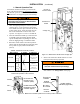
observe
these lights
Figure 1-4. Standard controls and indicators.
2–VoltageChecks
First check nameplate on transfer switch; rated voltage
mustbethesameasnormalandemergencylinevoltages.
Verify that the feeders have been
connected to the proper lugs.
Useextremecautionwhenusingameter
to measure voltages in the following
steps. Do not touch power terminals;
shock, burns, or death could result !
Perform steps 1 through 6 at the right. Observe the
status lights. See Figure 1–4.
Q Black square means light is on.
S White square means light is off.
* If necessary, adjust voltage regulator on the generator
according to the manufacturer’s recomm endations. The
Automatic Transfer Switch will respond onl y to the rated
vol tag e specified on the Tran sfer Switch namepl ate.
Note
Refer to Section 3 of Group 5 Controller User’s Guide
381333–126 for how to display the Status of the ATS
and the Voltage and Frequency of each source.
Now continue to 3 – Electrical Operation on next page.
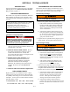
1
Close the normal source circuit
breaker. The Transfer Switch
Connected To Normal and the
Normal Source Accepted lights
should come on.
2
Use an accurate voltmeter to
check phase to phase and
phase to neutral voltages pres-
entatthetransferswitchnormal
source terminals.
3
Close the emergency source
circuit breaker. (Start generator,
if necessary.) The Transfer
Switch Connected To Normal &
Emergency Source Accepted
lights should come on.
4
Use an accurate voltmeter to
check phase to phase and
phase to neutral voltages pres-
ent a t the transfer sw itch emer -
gency source terminals.*
5
Useaphaserotationmeterto
check phase rotation of emer-
gency source; it must be the
same
as the normal source.
A
B
C
6
Shut down the engine–genera-
tor, if applicable. The Emergen-
cy Source Accepted light should
go off. Then put the starting
control selector switch (on the
generator set) in the automatic
position. Close enclosure door.