
Switch User Manual


INSTALLATION (continued)
1 --- 5
RED
RED
GREEN
GREEN
observe
these lights
operate
this switch
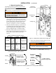
Figure 1-5. Standard controls and indicators.
3 – Electrical Operation
This procedure will check the electrical operation of
the Automatic Transfer Switch. See Figure 1–5.
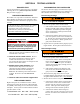
Be sure to close the enclosure door
before proceeding to prevent personal
injury in case of electrical system fault !
Transfer Test
Both normal and emergency sources must be available
and the emergency source generator (if used) must be
capable of being started in this procedure.
Perform steps 1 through 5 at the right. Observe the
status lights.
Q Black square means light is on.
S White square means light is off.
This completes the Functional Test of the ATS.
1
The Transfer Switch Connected
To Normal and Normal Source
Accepted lights should be on.
2
Turn and hold Transfer Control
switch clockwise to Transfer
Test until the engine starts
and runs (within 15 sec.).
Emergency Source Accepted
light should come on.
3
Transfer switch will operate to
the Emergency position after
Feature2Btimedelay.The
Transfer Switch Connected To
Emergency light should come
on and Load Connected to Nor-
mal light goes off.
4
Transfer switch will operate
back to Normal position after
Feature3Atimedelay.Forim-
mediate retransfer turn Tra nsf er
Control counterclockwise to
Retransfer Delay Bypass.The
Transfer Switch Connected To
Normal light should come on;
Transfer Switch Connected to
Emergency light should go off.
5
The engine–generator will stop
after the Feature 2E time delay
(unloaded running engine cool-
down). The Emergency Source
Accepted light should go off.