
Switch User Manual


SECTION 2 TESTING & SERVICE
2 --- 1
TRANSFER TEST
Operate the 7000 Series ATS at least once a month by
following the five–step Electrical Operation Transfer
Tes t procedure on page 1–5.
PREVENTIVE MAINTENANCE
Reasonable care in preventive maintenance will insure
high reliability and long life for the 7000 Series ATS.
An annual preventive maintenance program is recom-
mended.
In the United States, ASCO Services, Inc. (ASI) is
ASCO Po wer Technologies’s national se rvice
organization. ASI can be contacted at
1-800-800-2726 (ASCO) for information on
preventive maintenance agreements.
In Canada, for service call 1-800-234-2726 (ASCO).
Checklist f or Yearly Inspection
Hazardous voltage capable of causing shock,
burns, or death is used in this transfer switch.
Deenergize both Normal – Emergency power
sources before p erforming inspections!
S Clean the A TS enclosure. Brush and vacuum
away any excessive dust accumulation. Remove any
moisture with a clean cloth.
S Check the transfer switch contacts.Remove
the transfer switch barriers and check contact
condition. Reinstall barriers carefully. The
non–replaceable main contacts are designed to last
thelifeofthetransferswitch.
S Maintain transfer switch lubrication.Ifthe
transfer switch is subjected to severe dust or
abnor m al operating cond itions, renew factory
lubrication on all movements and linkages.
Relub r ic ate the so l en o id oper ato r if the TS c oil is
replaced. Do not use oil; order lubrication kit
75-100.
S Check all cable connections & retighten them.
REPLACEMENT PARTS
Replacement parts are available in kit form. When
ordering parts provide the Serial No., Bill of Material
No. (BOM), a nd Catalog No. from the transfer switch
nameplate. Contact your local ASCO Power Technolo-
gies Sales Office or ASI:
in United States call 1 800 – 800 – ASCO (2726)
or in Canada call 1 800 – 234 – ASCO (2726)
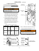
DISCONNECTING THE CONTROLLER
The harness disconnect plugs are furnished f or repair
purposes only and should not have to be unplugged. If
the controller must be isolated, follow these steps:
Disconnecting the Plugs
Do not unplug the controller until step
1a. or 1b. below is completed.
1. Observe the position of the transfer switch.
a. If the transfer switch is in the Normal position,
first plac e standby eng in e start ing con tr ol in the
off position. Second, then open the emergency
source circuit breaker. Third, open the normal
source circuit breaker.
b. If the transfer switch is i n the Emergency posi-
tion, fi rst open the normal source circuit break-
er. S econd, place the engine starting control in
the test or run position. Third, open the emer-
ge n cy so u r ce circuit break e r .
2. Separate the two q uick disconnect plugs by squeez-
ing the latches. Do not pull on the harness wires.
Reconnecting the Plugs
Do not reconnect the controll er until step
1a. or 1b. below is completed.
1. Observe the position of the transfer switch.
a. If the transfer switch is in the Normal position,
firstbesurethatboth
normal and emergency
source circui t breakers are open. Second, be
sure that the standby engine starting control is
still in the off position.
b. If the transfer switch is in the Emergency posi-
tion, first be sure that both
normal and emer-
gency source circuit breakers are open.
2. The two harness plugs and sockets are keyed.
Caref ully align the plugs with the sockets and press
straight in until both latches click. Close the door
!
3. Restore the two sources in sequence as follows:
a. If the transfer switch is in the Normal position,
first close the normal source circuit breaker.
Second, close the emergency source circuit
breaker. Third, place the standby engine
starting control in the automatic position.
b. If the transfer switch is i n the Emergency
position, first close the emergency source circuit
breaker. Second close the normal source circuit
breaker.