
User manual
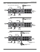
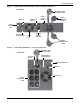

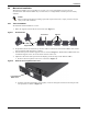
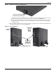
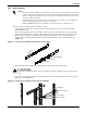
Table Of Contents
- Important Safety Precautions
- Save These Instructions
- Glossary of Symbols
- 1.0 Product Description
- 2.0 Installation
- 2.1 Unpacking and Inspection
- 2.2 What’s Included
- 2.3 Preparation for Installation
- 2.4 Mechanical Installation
- 2.4.1 Tower Installation
- 2.4.2 Rack Installation
- Figure 11 Pulling inner member from each slide rail assembly
- Figure 12 Installing rear member of each slide rail assembly
- Figure 13 Installing front member of each slide rail assembly
- Figure 14 Fastening rear member and front member together
- Figure 15 Installing inner members
- Figure 16 Installing rack-mount handles
- Figure 17 Insert the UPS
- 2.5 Cable Connection
- 2.6 Connecting Communication Cables
- 3.0 Controls and Indicators
- 4.0 Operation
- 5.0 Communication
- 6.0 Maintenance
- 7.0 Troubleshooting
- 8.0 Battery Cabinet
- 9.0 Specifications
- Table 11 Specifications of GXT3-500RT120 - GXT3-1000RT120 and GXT3-1000MT120 UPS
- Table 12 Specifications of GXT3-1500RT120 - GXT3-3000RT120 and GXT3-3000RT208 UPS
- Table 13 Battery cabinet specifications
- Table 14 Operating temperature parameters
- Table 15 Battery run times
- 9.1 Product Warranty Registration
Product Description
6
Figure 3 Liebert
®
GXT3
™
120V rack/tower models—rear panel components
Input Power Plug
and Cable 5-15P
External
Battery
Connector
Terminal Block
Communication
USB Port
Input Circuit
Breaker
Output
Receptacles,
5-15R
500VA, 700VA, 1000VA, 1500VA Models
Input Power Plug
and Cable, 5-20P
External
Battery
Connector
USB Port
Input Circuit
Breaker
Output
Receptacles,
5-15/20R
2000VA Model
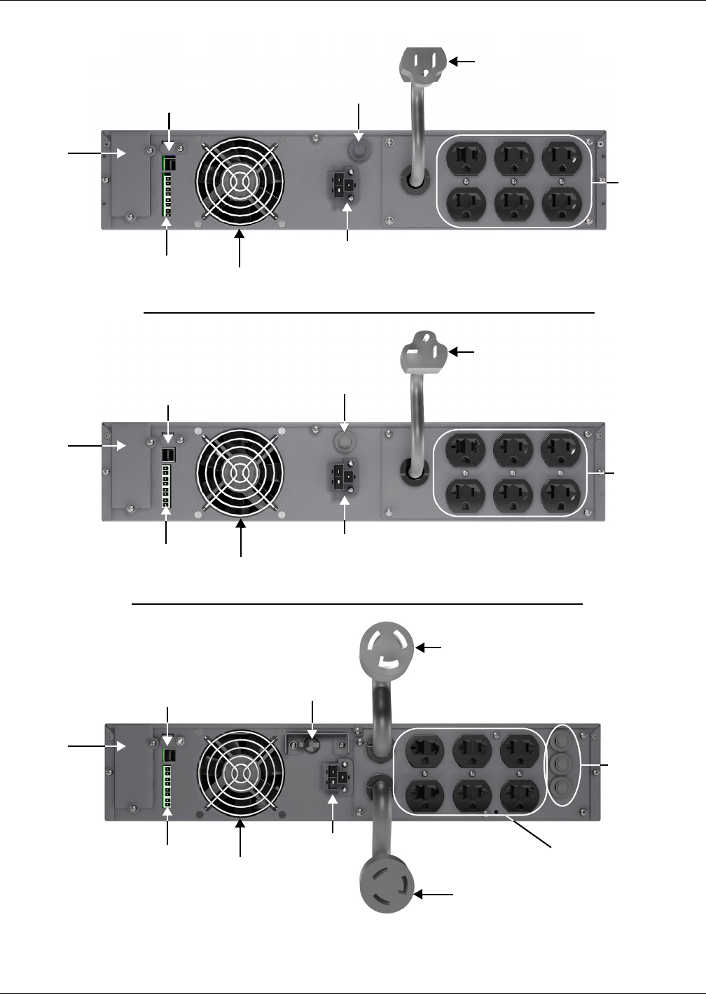
Input Power Plug
and Cable, L5-30P
USB Port
External
Battery
Connector
Input Circuit
Breaker
Output Receptacles,
5-15/20R
Output
Circuit
Breakers
3000VA Model
Liebert
IntelliSlot
Port
Liebert
IntelliSlot
Port
Liebert
IntelliSlot
Port
Terminal Block
Communication
Terminal Block
Communication
Output Receptacle,
L5-30R
Cooling
Fan
Cooling
Fan
Cooling
Fan