
User manual
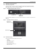
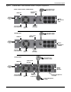
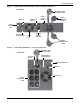

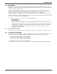
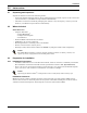
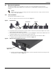
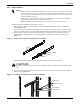
Table Of Contents
- Important Safety Precautions
- Save These Instructions
- Glossary of Symbols
- 1.0 Product Description
- 2.0 Installation
- 2.1 Unpacking and Inspection
- 2.2 What’s Included
- 2.3 Preparation for Installation
- 2.4 Mechanical Installation
- 2.4.1 Tower Installation
- 2.4.2 Rack Installation
- Figure 11 Pulling inner member from each slide rail assembly
- Figure 12 Installing rear member of each slide rail assembly
- Figure 13 Installing front member of each slide rail assembly
- Figure 14 Fastening rear member and front member together
- Figure 15 Installing inner members
- Figure 16 Installing rack-mount handles
- Figure 17 Insert the UPS
- 2.5 Cable Connection
- 2.6 Connecting Communication Cables
- 3.0 Controls and Indicators
- 4.0 Operation
- 5.0 Communication
- 6.0 Maintenance
- 7.0 Troubleshooting
- 8.0 Battery Cabinet
- 9.0 Specifications
- Table 11 Specifications of GXT3-500RT120 - GXT3-1000RT120 and GXT3-1000MT120 UPS
- Table 12 Specifications of GXT3-1500RT120 - GXT3-3000RT120 and GXT3-3000RT208 UPS
- Table 13 Battery cabinet specifications
- Table 14 Operating temperature parameters
- Table 15 Battery run times
- 9.1 Product Warranty Registration
Installation
12
2.4 Mechanical Installation
The Liebert
®
GXT3
™
may be installed as a tower or in a rack, depending on space and use
considerations. The Liebert GXT3 may be used alone, as a single UPS, or with up to four battery
cabinets.
2.4.1 Tower Installation
To install the Liebert GXT3 as a tower:
1. Take out support bases from the accessories (see Figure 7).
Figure 7 Support bases
2. If optional Liebert external battery cabinets will be connected to the Liebert GXT3, take out the
spacers shipped with the battery cabinet.
3. Connect the spacers and the support bases as shown in Figure 7. Each Liebert GXT3 needs two
assembled support bases, one in the front and one in the rear.
4. Adjust the direction of the operation and display panel and logo on the Liebert GXT3.
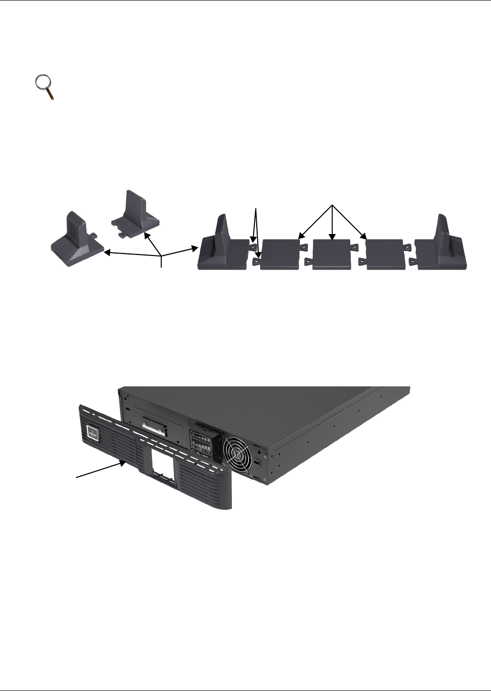
a. Remove the front plastic bezel cover as shown in Figure 8.
Figure 8 Remove the front plastic bezel cover
b. Pull the operation and display panel gently, rotate it 90 degrees clockwise and snap it back
into position, as shown in Figure 9.
NOTE
When installing the UPS or making input and output connections, comply with all relevant
safety codes and standards
Support Bases
Spacers
Connectors
Front Plastic
Bezel Cover