
User manual
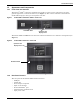
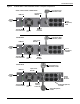
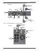

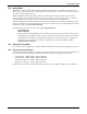
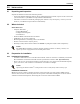
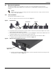
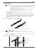
Table Of Contents
- Important Safety Precautions
- Save These Instructions
- Glossary of Symbols
- 1.0 Product Description
- 2.0 Installation
- 2.1 Unpacking and Inspection
- 2.2 What’s Included
- 2.3 Preparation for Installation
- 2.4 Mechanical Installation
- 2.4.1 Tower Installation
- 2.4.2 Rack Installation
- Figure 11 Pulling inner member from each slide rail assembly
- Figure 12 Installing rear member of each slide rail assembly
- Figure 13 Installing front member of each slide rail assembly
- Figure 14 Fastening rear member and front member together
- Figure 15 Installing inner members
- Figure 16 Installing rack-mount handles
- Figure 17 Insert the UPS
- 2.5 Cable Connection
- 2.6 Connecting Communication Cables
- 3.0 Controls and Indicators
- 4.0 Operation
- 5.0 Communication
- 6.0 Maintenance
- 7.0 Troubleshooting
- 8.0 Battery Cabinet
- 9.0 Specifications
- Table 11 Specifications of GXT3-500RT120 - GXT3-1000RT120 and GXT3-1000MT120 UPS
- Table 12 Specifications of GXT3-1500RT120 - GXT3-3000RT120 and GXT3-3000RT208 UPS
- Table 13 Battery cabinet specifications
- Table 14 Operating temperature parameters
- Table 15 Battery run times
- 9.1 Product Warranty Registration

Installation
14
2.4.2 Rack Installation
To install a Liebert GXT3 rack/tower UPS in a rack:
1. Unpack the two slide rails assemblies and mounting hardware from the rack-mounting kit
(P/N: RMKIT18-32).
Slide rail assembly includes inner member and front and rear members. They are interchange-
able between left-hand or right-hand. Mounting hardware includes M4 screws and M5 screws.
2. Remove inner member of each slide rail assembly by extending it to its outermost position,
depressing the retaining latch and then pulling inner member from slide rail assembly (see
Figure 11).
Figure 11 Pulling inner member from each slide rail assembly
3. Determine the Liebert GXT3’s mounting position inside the racks vertical rails.
4. Attach the rear member of each slide rail assembly to the rack’s rails with two factory-supplied
M5 screws (see Figure 12).
Figure 12 Installing rear member of each slide rail assembly
NOTE
• When the Liebert
®
GXT3
™
is installed in a rack, it must be supported by a shelf, fixed
rails or slide rails on each side. The factory-supplied rack mount handles cannot sup-
port the weight of the UPS. They are used to move the UPS into and out of the rack and
attach the UPS to the rack.
• Mounting hardware and slide rails are sold separately. Contact your local Emerson
representative for these options and any assistance.
• GXT3-1000MT120 cannot be installed in a rack. The unit is a minitower only.
!
CAUTION
Reduce the risk of tipping the rack by installing the Liebert GXT3 as low as possible in the
rack.
Slide rail assembly
Retaining latch
Inner member
P
u
l
l
o
u
t
M5 screw (4 pcs)
Vertical pole
Rear member
Front member