
Specifications

Quick Start Guide
11
May 2015
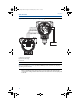
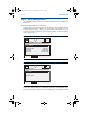
3. Replace the housing cover. It is recommended the cover be tightened until
there is no gap between the cover and the housing.
4. Plug and seal the unused conduit connection with the provided conduit plug.
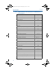
Remote display wiring and power up (if applicable)
The remote mount display and Interface system consists of a local transmitter
and a remote mount LCD display assembly. The local 3051S Transmitter assembly
includes a Junction Box housing with a three-position terminal block integrally
mounted to a sensor module. The remote mount LCD display assembly consists
of a dual compartment PlantWeb housing with a seven position terminal block.
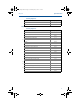
See Figure 9 on page 12 for complete wiring instructions. The following is a list of
necessary information specific to the remote mount display system:
Each terminal block is unique for the remote display system.
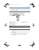
A 316 SST Housing Adaptor is permanently secured to the remote mount LCD
display PlantWeb housing, providing an external ground and a means for field
mounting with the provided mounting bracket.
A cable is required for wiring between the transmitter and remote mount LCD
display. The cable length is limited to 100 ft.
50 ft. (option M8) or 100 ft. (option M9) cable is provided for wiring between
the transmitter and remote mount LCD display. Option M7 does not include
cable; see recommended specifications below.
Cable type
Recommend Madison AWM Style 2549 cable. Other comparable cable may be
used as long as it has independent dual twisted shielded pair wires with an outer
shield. The power wires must be 22 AWG minimum and the CAN communication
wires must be 24 AWG minimum.
Cable length
The cable length is up to 100 feet depending upon cable capacitance.
Cable capacitance
The capacitance from the CAN communications line to the CAN return line as
wired must be less than 5000 picofarads total. This allows up to 50 picofarads per
foot for a 100 foot cable.
Intrinsic safety consideration
The transmitter assembly with remote display has been approved with Madison
AWM Style 2549 cable. Alternate cable may be used as long as the transmitter
with remote display and cable is configured according to the installation control
drawing or certificate. Refer to appropriate approval certificate or control
drawing in Appendix B of the 3051S Reference Manual for remote cable IS
requirements.
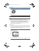
Important
Do not apply power to the remote communications terminal. Follow wiring instructions carefully
to prevent damage to system components.
4801_QIG_RevMA.fm Page 11 Wednesday, May 6, 2015 1:15 PM