
Specifications

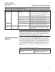
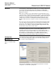

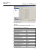
Table Of Contents
- Rosemount 3051S Series Scalable Pressure, Flow, and Level Solution with HART® Protocol
- Title Page
- Table of Contents
- Section 1 Introduction
- Section 2 Installation
- Section 3 Configuration
- Section 4 Operation and Maintenance
- Section 5 Troubleshooting
- Section 6 Safety Instrumented Systems
- Section 7 Advanced HART Diagnostic Suite
- Appendix A Specifications and Reference Data
- Appendix B Product Certifications
- Index
Reference Manual
00809-0100-4801, Rev FA
October 2010
Rosemount 3051S Series
7-24
Troubleshooting
DIAGNOSTIC LOG
Overview The Diagnostic Log provides a history of the last ten transmitter alerts and
time stamp of when they occurred. This allows the user to reference a
sequence of events or alerts to aid the troubleshooting process. The log
prioritizes and manages the alerts in a first-in, first-out manner. This log is
stored in the non-volatile internal memory of the 3051S transmitter. If power is
removed from transmitter, the log remains intact and can be viewed again
when powered up.
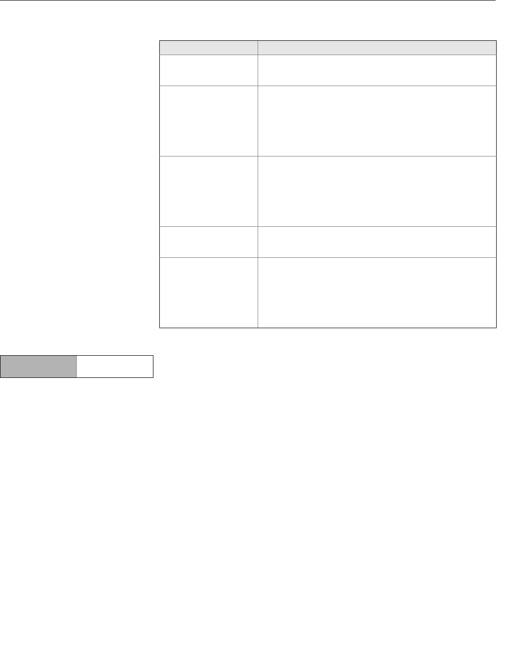
Table 7-8. Possible Power Advisory issues and resolutions
Issue Resolution
Transmitter automatically
resets upon annunciation
of HIGH alarm.
The loop has been severely degraded and the transmitter does not
have enough voltage to generate a HIGH alarm. Transmitter reset
will create a low off-scale reading. Repair damaged loop.
Transmitter does not
generate LOW alarm
value when it should.
The loop has been severely degraded and the host system is not
able to read the proper mA output from the transmitter. This may
occur if water floods the terminal compartment and “shorts out” the
+ to – terminals or the terminals to chassis. This is most likely to
occur if the loop resistor is connected to the + side of the power
supply. Repair the damaged loop. Consider setting alarm direction
to HIGH.
Transmitter does not
generate HIGH alarm
value.
The loop has been severely degraded and the host system is not
able to read the proper mA output from the transmitter. This may
occur if water floods the terminal compartment and “shorts out” the
+ to – terminals or the terminals to chassis. This is most likely to
occur if the loop resistor is connected to the – side of the power
supply and is earth grounded. Repair the damaged loop. Consider
setting alarm direction to LOW.
Diagnostic does not
detect a damaged loop.
Diagnostic will not trip if loop characterization was performed when
the loop was already damaged. Repair damaged loop and
re-characterize.
Diagnostic is detecting
false alarms or alerts.
Re-characterize the loop and compare the baseline with the
previous baseline. Resistance changes may indicate poor or
intermittent connections. Power supply voltage changes may
indicate unstable supply. Test for the presence of AC voltage using
an AC DVM or oscilloscope. Adding an amp meter across the test
diode will cause voltage changes of up to 1V. If all conditions look
acceptable, increase the terminal voltage deviation.
Device Dashboard
Fast Keys
3, 4, 2