4801_QIG_RevHA.
4801_QIG_RevHA.fm Page 2 Tuesday, February 26, 2008 12:17 PM Quick Installation Guide Rosemount 3051S Rosemount Inc. 8200 Market Boulevard Chanhassen, MN USA 55317 T (US) (800) 999-9307 T (Intnl) (952) 906-8888 F (952) 949-7001 00825-0100-4801, Rev HA February 2008 Emerson Process Management GmbH & Co. OHG Argelsrieder Feld 3 82234 Wessling Germany T 49 (8153) 9390, F49 (8153) 939172 Emerson Process Management Asia Pacific Private Limited Beijing Rosemount Far East Instrument Co.
4801_QIG_RevHA.fm Page 3 Tuesday, February 26, 2008 12:17 PM Quick Installation Guide 00825-0100-4801, Rev HA February 2008 Rosemount 3051S WARNING Explosions could result in death or serious injury: Installation of this transmitter in an explosive environment must be in accordance with the appropriate local, national, and international standards, codes, and practices. Please review the approvals section of the 3051S reference manual for any restrictions associated with a safe installation.
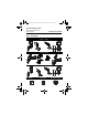
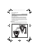
801_QIG_RevHA.fm Page 4 Tuesday, February 26, 2008 12:17 PM Quick Installation Guide Rosemount 3051S 00825-0100-4801, Rev HA February 2008 STEP 1: MOUNT THE TRANSMITTER Liquid Flow Applications 1. Place taps to the side of the line. 2. Mount beside or below the taps. 3. Mount the transmitter so that the drain/vent valves are oriented upward. Gas Flow Applications 1. Place taps in the top or side of the line. 2. Mount beside or above the taps. Steam Flow Applications 1.
4801_QIG_RevHA.fm Page 5 Tuesday, February 26, 2008 12:17 PM Quick Installation Guide 00825-0100-4801, Rev HA February 2008 Rosemount 3051S STEP 1 CONTINUED...
4801_QIG_RevHA.fm Page 6 Tuesday, February 26, 2008 12:17 PM Quick Installation Guide 00825-0100-4801, Rev HA February 2008 Rosemount 3051S STEP 2: CONSIDER HOUSING ROTATION To improve field access to wiring or to better view the optional LCD display: 1. Loosen the housing rotation set screw. 2. First rotate the housing clockwise to the desired location.
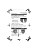
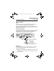
4801_QIG_RevHA.fm Page 7 Tuesday, February 26, 2008 12:17 PM Quick Installation Guide 00825-0100-4801, Rev HA February 2008 Rosemount 3051S STEP 4: CONNECT WIRING AND POWER UP Use the following steps to wire the transmitter: 1. Remove the housing cover labeled “Field Terminals.” 2. Connect the positive lead to the “+” terminal, and the negative lead to the “–” terminal. NOTE Do not connect the power across the test terminals. Power could damage the test diode in the test connection.
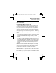
4801_QIG_RevHA.fm Page 8 Tuesday, February 26, 2008 12:17 PM Quick Installation Guide Rosemount 3051S 00825-0100-4801, Rev HA February 2008 STEP 4 CONTINUED... Remote Display Wiring and Power Up The Remote Mount Display and Interface system consists of a local transmitter and a remote mount LCD display assembly. The local 3051S transmitter assembly includes a Junction Box housing with a three position terminal block integrally mounted to a SuperModule.
4801_QIG_RevHA.fm Page 9 Tuesday, February 26, 2008 12:17 PM Quick Installation Guide 00825-0100-4801, Rev HA February 2008 Rosemount 3051S STEP 4 CONTINUED... Intrinsic Safety Consideration: The transmitter assembly with remote display has been approved with Belden 3084A DeviceNet cable. Alternate cable may be used as long as the transmitter with remote display and cable is configured according to the installation control drawing or certificate.
4801_QIG_RevHA.fm Page 10 Tuesday, February 26, 2008 12:17 PM Quick Installation Guide Rosemount 3051S 00825-0100-4801, Rev HA February 2008 STEP 4 CONTINUED... NOTE Wire colors provided on page 9 are per Belden 3084A DeviceNet cable. Wire color may vary depending on cable selected. Belden 3084A DeviceNet cable includes a ground shield. This shield must be connected to earth ground at either the SuperModule or the Remote Display, but not both.
4801_QIG_RevHA.fm Page 11 Tuesday, February 26, 2008 12:17 PM Quick Installation Guide 00825-0100-4801, Rev HA February 2008 Rosemount 3051S STEP 4 CONTINUED... 2. Place coupling nut over quick connect and wrench tighten to a maximum of 300 in-lb. (34 N-m). 3. Tighten the set screw using a 3/32-in hex wrench. 4. Install Cordset/ Field Wireable Connectors onto the Quick Connect. Do not over tighten. Figure 6.
4801_QIG_RevHA.fm Page 12 Tuesday, February 26, 2008 12:17 PM Quick Installation Guide 00825-0100-4801, Rev HA February 2008 Rosemount 3051S STEP 4 CONTINUED... Power Supply The dc power supply should provide power with less than two percent ripple. The total resistance load is the sum of the resistance of the signal leads and the load resistance of the controller, indicator, and related pieces. Note that the resistance of intrinsic safety barriers, if used, must be included. Figure 7.
4801_QIG_RevHA.fm Page 13 Tuesday, February 26, 2008 12:17 PM Quick Installation Guide 00825-0100-4801, Rev HA February 2008 Rosemount 3051S STEP 5: VERIFY CONFIGURATION Use any HART-compliant master to communicate with and verify configuration of the 3051S. For the HART Diagnostics transmitter (option code DA1), DD revision 3051S HDT Dev. 1 Rev. 1 is required. A check (⻫) indicates the basic configuration parameters.
4801_QIG_RevHA.fm Page 14 Tuesday, February 26, 2008 12:17 PM Quick Installation Guide Rosemount 3051S 00825-0100-4801, Rev HA February 2008 STEP 5 CONTINUED...
4801_QIG_RevHA.fm Page 15 Tuesday, February 26, 2008 12:17 PM Quick Installation Guide 00825-0100-4801, Rev HA February 2008 Rosemount 3051S STEP 6: TRIM THE TRANSMITTER Transmitters are shipped fully calibrated per request or by the factory default of full scale (lower range value = zero, upper range value = upper range limit). Zero Trim A zero trim is a single-point adjustment used for compensating mounting position and line pressure effects.
4801_QIG_RevHA.fm Page 16 Tuesday, February 26, 2008 12:17 PM Quick Installation Guide Rosemount 3051S 00825-0100-4801, Rev HA February 2008 Using the Transmitter Zero Adjustment Button Push and hold the zero adjustment button for at least two seconds but no longer than ten seconds. Figure 8.
4801_QIG_RevHA.fm Page 17 Tuesday, February 26, 2008 12:17 PM Quick Installation Guide 00825-0100-4801, Rev HA February 2008 Rosemount 3051S SAFETY INSTRUMENTED SYSTEMS Additional Safety Instrumented Systems information is available in the Rosemount 3051S reference manual (document number 00809-0100-4801). The manual is available electronically on www.rosemount.com or by contacting an Emerson Process Management representative.
4801_QIG_RevHA.fm Page 18 Tuesday, February 26, 2008 12:17 PM Quick Installation Guide Rosemount 3051S 00825-0100-4801, Rev HA February 2008 Installation No special installation is required in addition to the standard installation practices outlined in this document. Always ensure a proper seal by installing the electronics housing covers so that metal contacts metal. The loop should be designed so the terminal voltage does not drop below 10.5 Vdc when the transmitter output is 23.0 mA.
4801_QIG_RevHA.fm Page 19 Tuesday, February 26, 2008 12:17 PM Quick Installation Guide 00825-0100-4801, Rev HA February 2008 Rosemount 3051S NOTES 1. Transmitter output is not safety-rated during the following: configuration changes, multidrop, loop test. Alternative means should be used to ensure process safety during transmitter configuration and maintenance activities. 2. DCS or safety logic solver should be configured to match transmitter configuration.
4801_QIG_RevHA.fm Page 20 Tuesday, February 26, 2008 12:17 PM Quick Installation Guide Rosemount 3051S 00825-0100-4801, Rev HA February 2008 Setting the alarm values and direction is dependent on whether or not the hardware switch option is installed. You can use a HART master or communicator to set the Alarm and Saturation values. Switches installed 1. If using a communicator, use the following fast key sequence to set the Alarm and Saturation values.
4801_QIG_RevHA.fm Page 21 Tuesday, February 26, 2008 12:17 PM Quick Installation Guide 00825-0100-4801, Rev HA February 2008 Rosemount 3051S Operation and Maintenance Proof Test and Inspection The following proof tests are recommended. Proof test results and corrective actions taken must be documented at www.emersonprocess.com/rosemount/safety/certtechdocumentation. htm in the event that an error is found in the safety functionality.
4801_QIG_RevHA.fm Page 22 Tuesday, February 26, 2008 12:17 PM Quick Installation Guide Rosemount 3051S 00825-0100-4801, Rev HA February 2008 Proof Test 2 This proof test, when combined with the Proof Test 1, will detect over 92% of DU failures not detected by the 3051S_C or 3051S_L automatic diagnostics, and over 95% of DU failures not detected by the 3051S_T automatic diagnostics. Required tools: HART host/communicator and pressure calibration equipment. 1.
4801_QIG_RevHA.fm Page 23 Tuesday, February 26, 2008 12:17 PM Quick Installation Guide 00825-0100-4801, Rev HA February 2008 Rosemount 3051S Reference Certification The 3051S Safety-Certified Pressure Transmitter was designed, developed, and audited to be compliant to IEC 61508 safety-certified SIL 2 Claim Limit. Specifications The 3051S Safety-Certified Pressure Transmitter must be operated in accordance to the functional and performance specifications provided in the 3051S reference manual.
4801_QIG_RevHA.fm Page 24 Tuesday, February 26, 2008 12:17 PM Quick Installation Guide Rosemount 3051S 00825-0100-4801, Rev HA February 2008 PRODUCT CERTIFICATIONS Approved Manufacturing Locations Rosemount Inc. — Chanhassen, Minnesota USA Fisher-Rosemount GmbH & Co. — Wessling, Germany Emerson Process Management Asia Pacific Private Limited — Singapore Beijing Rosemount Far East Instrument Co.
4801_QIG_RevHA.fm Page 25 Tuesday, February 26, 2008 12:17 PM Quick Installation Guide 00825-0100-4801, Rev HA February 2008 Rosemount 3051S Hazardous Locations Certifications North American Certifications FM Approvals E5 Explosion proof for Class I, Division 1, Groups B, C, and D; dust-ignition proof for Class II and Class III, Division 1, Groups E, F, and G; hazardous locations; enclosure Type 4X, conduit seal not required when installed according to Rosemount drawing 03151-1003.
4801_QIG_RevHA.fm Page 26 Tuesday, February 26, 2008 12:17 PM Quick Installation Guide 00825-0100-4801, Rev HA February 2008 Rosemount 3051S European Certifications I1 ATEX Intrinsic Safety Certificate No.: BAS01ATEX1303X II 1 G EEx ia IIC T4 (Ta = -60 °C to 70 °C) -HART/Remote Display/Quick Connect/HART Diagnostics 1180 Table 2. Input Parameters Loop / Power Groups Ui = 30V Ii = 300 mA Pi = 1.0W Ci = 30nF Ci = 11.
4801_QIG_RevHA.fm Page 27 Tuesday, February 26, 2008 12:17 PM Quick Installation Guide 00825-0100-4801, Rev HA February 2008 Rosemount 3051S Special Conditions for Safe Use (x) The apparatus is not capable of withstanding the 500V insulation test required by Clause 9.1 of EN 50021: 1999. This must be taken into account when installing the apparatus. ND ATEX Dust Certificate No.: BAS01ATEX1374X II 1 D T105°C (-20 °C ≤ Tamb ≤ 85 °C) Vmax = 42.
4801_QIG_RevHA.fm Page 28 Tuesday, February 26, 2008 12:17 PM Quick Installation Guide Rosemount 3051S E1 ATEX Flame-Proof Certificate No.: KEMA00ATEX2143X EEx d IIC T6 (-50 °C ≤ Tamb ≤ 65 °C) EEx d IIC T5 (-50 °C ≤ Tamb ≤ 80 °C) Vmax = 42.4V 1180 00825-0100-4801, Rev HA February 2008 II 1/2 G Special conditions for safe use (x) This device contains a thin wall diaphragm. Installation, maintenance and use shall take into account the environmental conditions to which the diaphragm will be subjected.
4801_QIG_RevHA.fm Page 29 Tuesday, February 26, 2008 12:17 PM Quick Installation Guide 00825-0100-4801, Rev HA February 2008 Rosemount 3051S Australian Certifications E7 SAA Explosion-Proof and Dust Ignition-Proof Certification No.: AUS Ex 3798X Ex d IIC T6 (Ta = 60°C) IP66 DIP A21 TA T6 (Ta = 60°C) IP66 Conditions for safe use (X) 1. It is a condition of safe use that each housing shall be connected to external circuits via suitable conduit of Standards Australia certified cable glands.
4801_QIG_RevHA.fm Page 30 Tuesday, February 26, 2008 12:17 PM Quick Installation Guide 00825-0100-4801, Rev HA February 2008 Rosemount 3051S I7 IECEx Intrinsic Safety Certificate No.: IECExBAS04.0017X Ex ia IIC T4 (Ta = -60 °C to 70 °C) -HART/Remote Display/Quick Connect/HART Diagnostics IP66 Table 4. Input Parameters Loop / Power Groups Ui = 30V Ii = 300 mA Pi = 1.0W Ci = 30nF Ci = 11.
4801_QIG_RevHA.fm Page 31 Tuesday, February 26, 2008 12:17 PM Quick Installation Guide 00825-0100-4801, Rev HA February 2008 Rosemount 3051S Combinations of Certifications Stainless steel certification tag is provided when optional approval is specified. Once a device labeled with multiple approval types is installed, it should not be reinstalled using any other approval types. Permanently mark the approval label to distinguish it from unused approval types.
4801_QIG_RevHA.
4801_QIG_RevHA.
4801_QIG_RevHA.
4801_QIG_RevHA.
4801_QIG_RevHA.