Instruction Manual PN 51-396R/rev.
DANGER ESSENTIAL INSTRUCTIONS READ THIS PAGE BEFORE PROCEEDING! Rosemount Analytical designs, manufactures, and tests its products to meet many national and international standards. Because these instruments are sophisticated technical products, you must properly install, use, and maintain them to ensure they continue to operate within their normal specifications.
MODEL 396R pH/ORP TABLE OF CONTENTS MODEL 396R AND 396RVP RETRACTABLE pH/ORP SENSORS TABLE OF CONTENTS Section 1.0 1.1 1.2 1.3 Title DESCRIPTION AND SPECIFICATIONS........................................................... Features and Applications................................................................................. Performance and Physical Specifications ......................................................... Ordering Information ............................................................
MODEL 396R pH/ORP TABLE OF CONTENTS LIST OF FIGURES Figure No. 1-1 2-1 2-2 2-3 2-4 2-5 2-6 2-7 2-8 3-1 3-2 3-3 3-4 3-5 3-6 3-7 3-8 3-9 3-10 3-11 3-12 3-13 3-14 3-15 4-1 4-2 4-3 4-4 4-5 4-6 4-7 4-8 4-9 4-10 4-11 4-12 4-13 4-14 4-15 4-16 4-17 4-18 4-19 4-20 4-21 6-1 6-2 Title Cross Section Diagram of the TUpH Reference Technology ............................ Exploded View of Ball Valve Kit PN 23240-00 used with process connector . PN 23166-00 (or PN 23166-01) ...............................................
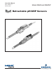
MODEL 396R pH/ORP SECTION 1.0 DESCRIPTION AND SPECIFICATIONS SECTION 1.0 DESCRIPTION AND SPECIFICATIONS 1.1 FEATURES AND APPLICATIONS The Model 396R and 396RVP Sensors are specifically designed for improved life in harsh, dirty applications where a separate sample stream is difficult to provide and greater insertion depths are required. Model 396R is designed for use with a 1-1/4 in. or 1-1/2 in. ball valve for hot tap installation.
MODEL 396R pH/ORP 1.2 SECTION 1.
MODEL 396R pH/ORP SECTION 1.0 DESCRIPTION AND SPECIFICATIONS 1.3 ORDERING INFORMATION The Model 396R Sensor is housed in a titanium tube, with a polypropylene reference junction and titanium solution ground for use with a ball valve (order separately) for hot tap applications. The sensor is available with either a hemi or flat glass pH electrode and features a shrouded glass/platinum electrode and PT100 or 3K temperature compensation. The 396R is available with 9.5 in. or 15 ft of integral cable.
MODEL 396R pH/ORP SECTION 1.0 DESCRIPTION AND SPECIFICATIONS TABLE 1-1. COMMONLY USED ACCESSORIES FOR MODEL 396R For first time installations, Rosemount Analytical recommends using the following guide 1. Retractable Mounting A. Choose one (required for all first time installations): PN 23166-00, 1 in. x 1 in. NPT process connector, 316 SST PN 23166-01, 1 in. x 1 in. NPT process connector, Titanium B. Choose one: PN 23240-00, 1-1/2 in. ball valve assembly, 316 SST PN 23765-00, 1-1/4 in.
MODEL 396R pH/ORP SECTION 1.0 DESCRIPTION AND SPECIFICATIONS TABLE 1-3. COMMONLY USED ACCESSORIES FOR MODEL 396RVP FOR FIRST TIME 396RVP AND 398RVP INSTALLATIONS, ROSEMOUNT ANALYTICAL RECOMMENDS USING THE FOLLOWING GUIDE: 1. Variopol Cable (required for all first time installations) Choose one: PN 23645-06, 15 ft cable with mating VP connector, prepped with BNC on analyzer end PN 23645-07, 15 ft cable with mating VP connector, prepped without BNC on analyzer end* 2. Retractable Mounting 1A.
MODEL 396R pH/ORP SECTION 2.0 INSTALLATION SECTION 2.0 INSTALLATION 2.1 UNPACKING AND INSPECTION. Inspect the outside of the carton for any damage. If damage is detected, contact the carrier immediately. Inspect the instrument and hardware. Make sure all items in the packing list are present and in good condition. Notify the factory if any part is missing. NOTE If the sensor is to be stored, the protective boot should be filled with either KCl electrolyte solution or pH 4.
MODEL 396R pH/ORP 6. SECTION 2.0 INSTALLATION While holding the sensor in position, tighten the hex nut of the male connector to firmly secure the sensor in place. When the hex nut is tightened, the Teflon ferrule inside the compression fitting clamps the sensor tube. 2.2.2 INSTALLATION WITHOUT A BALL VALVE. The Model 396R Sensor may be installed through a weldalet or pipe tee or “Y” when used with a process connector (PN 23166-00 or 23166-01).
MODEL 396R pH/ORP SECTION 2.0 INSTALLATION JUNCTION BOX IS OPTIONAL FIGURE 2-2. Typical Mounting Configurations for Model 396R FIGURE 2-3.
MODEL 396R pH/ORP SECTION 2.0 INSTALLATION INCH MILLIMETER FIGURE 2-4. Dimensional Drawing — Model 396R with Optional Ball Valve PN 23765-00 Note: Add five (5) inches to dimension A if mounting a sensor head junction box onto the sensor.
MODEL 396R pH/ORP SECTION 2.0 INSTALLATION WHEN INCH AND METRIC DIMS ARE GIVEN MILLIMETER INCH DWG. NO. 40396R05 FIGURE 2-5. Dimensional Drawing — Model 396R with Optional Ball Valve PN 23240-00 Note: Add five (5) inches to dimension A if mounting a sensor head junction box onto the sensor. 10 REV.
MODEL 396R pH/ORP SECTION 2.0 INSTALLATION MILLIMETER INCH 4.920 Front Side 396R-21 Note: Retraction Pressure 2.25 36” 36” Back Side 396R Front Side 396R-25 Note: Retraction Pressure A MM / IN 548.64 / 21.60 916.94 / 36.10 OPTION 21 25 FIGURE 2-6. Dimensional Warning Label for Model 396R Hemi Bulb Sensors and Sensor Diagram Note: Pressure rating for flat glass sensors is 100-790 kPa (0-100 psig).
MODEL 396R pH/ORP SECTION 2.0 INSTALLATION WHEN INCH AND METRIC DIMS ARE GIVEN MILLIMETER INCH FIGURE 2-7.
MODEL 396R pH/ORP SECTION 2.0 INSTALLATION INCH MILLIMETER FIGURE 2-8.
MODEL 396R pH/ORP SECTION 3.0 WIRING MODEL 396R SECTION 3.0 WIRING MODEL 396R WIRING MODEL 396R. Make electrical connections as shown on Figures 3-1 through 3-15 using the following guidelines. For wiring Model 396RVP, see Section 4.0. 1. Pay particular attention to the analyzer or transmitter model number when following details on the wiring diagrams to ensure that the connections are made to the proper terminals. 2. Use Rosemount custom cable Part Number 9200273 for interconnect. 3.
MODEL 396R pH/ORP SECTION 3.0 WIRING MODEL 396R DWG. NO. 40396R07 REV. D FIGURE 3-2. Wiring Model 396R-54 to Models 54e, 81, 3081, 4081, and 5081 pH/ORP WHEN INCH AND METRIC DIMS ARE GIVEN MILLIMETER INCH MODELS 54e, 81, 3081, 4081, 5081 DWG. NO. 40396R08 REV. B FIGURE 3-3.
MODEL 396R pH/ORP SECTION 3.0 WIRING MODEL 396R DANGER: Do not connect sensor cable to power lines. Serious injury may result. 1 PREP ORANGE WIRE FOR PREAMP WITH BNC ADAPTER (PN 9120516). DWG. NO. 40396R011 REV. A FIGURE 3-4. Wiring Model 396R-50 for use with Remote Junction Box (PN 23309-03) DANGER: Do not connect sensor cable to power lines. Serious injury may result. 1 PREP ORANGE WIRE FOR PREAMP WITH BNC ADAPTER (PN 9120516). DWG. NO. 40396R012 FIGURE 3-5.
MODEL 396R pH/ORP SECTION 3.0 WIRING MODEL 396R DWG. NO. REV. 40396R09 A FIGURE 3-6. Wiring Model 396R-50/54 to Model 1181 pH/ORP 1 PREP ORANGE WIRE FOR PREAMP WITH BNC ADAPTER (PN 9120516). DWG. NO. REV. 40396R010 A FIGURE 3-7.
MODEL 396R pH/ORP SECTION 3.0 WIRING MODEL 396R DWG. NO. 40396R13 FIGURE 3-8. Wiring Model 396R-54 to Model SCL-(P/Q) FIGURE 3-9. Wiring Model 396R-54-61 to Model Xmt-P-XX-10 18 REV.
MODEL 396R pH/ORP SECTION 3.0 WIRING MODEL 396R WHEN INCH AND METRIC DIMS ARE GIVEN MILLIMETER INCH DWG. NO. REV. 40396R21/22 C/C FIGURE 3-10. Wiring Model 396R-50/54-60 for use with Sensor Head J-Boxes to Models 1181, 1054 Series, 2054, 2081 MODELS 54e, 81, 3081, 4081, 5081 DWG. NO. 40396R06 REV. C FIGURE 3-11.
MODEL 396R pH/ORP SECTION 3.0 WIRING MODEL 396R MILLIMETER INCH DWG. NO. 40396R21 FIGURE 3-12. Wiring Model 396R-50 for use with J-Box (PN 23707-00) to Models 1181, 1050, 1060, 1030, and 1023 pH Transmitters 20 REV.
MODEL 396R pH/ORP SECTION 3.0 WIRING MODEL 396R DWG. NO. 40396R22 REV. C FIGURE 3-13.
MODEL 396R pH/ORP SECTION 3.0 WIRING MODEL 396R FIGURE 3-14. Wiring Model 396R-( )-54 to Model 1055-10-22-32 FIGURE 3-15.
MODEL 396R pH/ORP SECTION 4.0 WIRING MODEL 396RVP SECTION 4.0 WIRING MODEL 396RVP WIRING MODEL 396RVP. Make electrical connections as shown on Figures 4-1 through 4-21 using the following guidelines. For wiring Model 396R, see Section 3.0. 1. Pay particular attention to the analyzer or transmitter model number when following details on the wiring diagrams to ensure that the connections are made to the proper terminals. 2. The Model 396RVP uses a mating VP cable.
MODEL 396R pH/ORP 24 SECTION 4.0 WIRING MODEL 396RVP FIGURE 4-2. Model 81 Wiring FIGURE 4-3. Model 1181 Wiring FIGURE 4-4. Model 81 Wiring through Remote Junction Box FIGURE 4-5.
MODEL 396R pH/ORP SECTION 4.0 WIRING MODEL 396RVP FIGURE 4-6. Model 2081 Wiring FIGURE 4-7. Model 3081, 4081, and 5081 Wiring FIGURE 4-8. Model 2081 Wiring through Remote Junction Box FIGURE 4-9.
MODEL 396R pH/ORP SECTION 4.0 WIRING MODEL 396RVP FIGURE 4-10. Model 1054 Wiring FIGURE 4-11. Model 1054A/B & 2054 Wiring FIGURE 4-12. Model 1054 Wiring through a Remote Junction Box FIGURE 4-13.
MODEL 396R pH/ORP FIGURE 4-14. Model 54/54e Wiring SECTION 4.0 WIRING MODEL 396RVP FIGURE 4-15. Model 54 Wiring through Remote Junction Box FIGURE 4-17. Model SCL-(P/Q) Wiring FIGURE 4-16.
MODEL 396R pH/ORP SECTION 4.0 WIRING MODEL 396RVP FIGURE 4-18. Model Xmt-P-XX-10 Wiring FIGURE 4-19. Model 1055pH/pH Wiring FIGURE 4-20.
MODEL 396R pH/ORP SECTION 4.0 WIRING MODEL 396RVP VARIOPOL CABLE PN 23645-07 FIGURE 4-21.
MODEL 396R pH/ORP SECTION 5.0 START UP AND CALIBRATION SECTION 5.0 START UP AND CALIBRATION 5.1 START UP. To obtain best accuracy, the sensor must be calibrated as a loop with the analyzer. Please refer to the respective analyzer/transmitter instruction manual for proper calibration procedures. 5.2 396R pH CALIBRATION 1. After a temporary connection is established between the sensor and the instrument, a buffer calibration may be performed. 2.
MODEL 396R pH/ORP SECTION 5.0 START UP AND CALIBRATION 5.3 396R ORP CALIBRATION. An ORP loop is best calibrated using an ORP standard solution. Most industrial applications have a number of ORP reactions occurring in sequence or simultaneously. There can be several components that are oxidized or reduced by the reagents that are used. Theoretically, the ORP potential is absolute because it is the result of the oxidation-reduction equilibrium.
MODEL 396R pH/ORP SECTION 6.0 MAINTENANCE SECTION 6.0 MAINTENANCE 6.1 Maintenance. The Model 396R Sensor is a disposal type sensor and therefore requires minimum maintenance. The sensor should be removed from the process periodically and checked in buffer solutions. If the sensor will not calibrate, refer to your analyzer/transmitters instruction manual for proper test procedures. If the sensor has failed, it should be discarded and replaced. 6.2 Sensor Removal.
MODEL 396R pH/ORP 4. 5. SECTION 6.0 MAINTENANCE TABLE 6-2 TEMPERATURE vs RESISTANCE OF AUTO T.C. ELEMENTS Following the caution above, wash the glass bulb in dilute 5% hydrochloric acid solution and then rinse it thoroughly in tap water. Replace the sensor if it cannot be cleaned. If the glass bulb appears clean, proceed to step 5. Temperature °C Buffer calibrate the sensor (Refer to Section 5.0).
MODEL 396R pH/ORP 4. SECTION 6.0 MAINTENANCE Discard used O-ring from male connector body (A). Coat new O-ring with a thin film of the O-ring lubricant provided. Position it in the machined Oring groove in place of the discarded O-ring. CAUTION Make sure lubricant does not contact any part of the sensor tip particularly the glass bulb. 5. 6. 7. Cover the 1" MNPT pipe threads of the male connector body (A) with Teflon tape (not provided) to protect them from galling during reinstallation.
MODEL 396R pH/ORP SECTION 6.0 MAINTENANCE FIGURE 6-1. Example of Sensor Tube Replacement FIGURE 6-2.
MODEL 396R pH/ORP SECTION 7.0 DIAGNOSTICS AND TROUBLESHOOTING SECTION 7.0 DIAGNOSTICS AND TROUBLESHOOTING 7.1 DIAGNOSTICS AND TROUBLESHOOTING WITH MODEL 54/81/3081 pH/ORP. The Model 54 and 54e Analyzers and Models 81 and 3081 pH Transmitters automatically search for fault conditions that would cause an error in the measured pH value, as does the Model 1054A/B pH/ORP Analyzer to a lesser degree. Refer to the respective manual for a complete description of the analyzer’s fault conditions.
MODEL 396R pH/ORP SECTION 7.0 DIAGNOSTICS AND TROUBLESHOOTING 7.2 TROUBLESHOOTING WITHOUT DIAGNOSTICS. Table 7-2 lists common problems, causes and remedies typically encountered in process measurement. TABLE 7-2. Troubleshooting without Diagnostics Problem Probable Cause Remedy Meter reads off scale. (Display reads overrange). Defective preamplifier. Replace preamplifier (for code 02 sensors). For code 01, replace sensor. T.C. element shorted. Check T.C. element as instructed in Section 6.
Model 396R pH/ORP SECTION 8.0 RETURN OF MATERIAL SECTION 8.0 RETURN OF MATERIAL 8.1 GENERAL. 8.3 NON-WARRANTY REPAIR. To expedite the repair and return of instruments, please call 1-949-757-8500 for a R e t u r n M a t e r i a l s Authorization (RMA) number. The following is the procedure for returning for repair instruments that are no longer under warranty: 1. Call Rosemount Analytical for authorization. 8.2 WARRANTY REPAIR. 2.
WARRANTY Seller warrants that the firmware will execute the programming instructions provided by Seller, and that the Goods manufactured or Services provided by Seller will be free from defects in materials or workmanship under normal use and care until the expiration of the applicable warranty period. Goods are warranted for twelve (12) months from the date of initial installation or eighteen (18) months from the date of shipment by Seller, whichever period expires first.
The right people, the right answers, right now. ON-LINE ORDERING NOW AVAILABLE ON OUR WEB SITE http://www.raihome.com Specifications subject to change without notice. 8 Credit Cards for U.S. Purchases Only. Emerson Process Management 2400 Barranca Parkway Irvine, CA 92606 USA Tel: (949) 757-8500 Fax: (949) 474-7250 http://www.raihome.com © Rosemount Analytical Inc.