Instruction Manual PN 51-396/397/398/rev.
ESSENTIAL INSTRUCTIONS READ THIS PAGE BEFORE PROCEEDING! Rosemount Analytical designs, manufactures, and tests its products to meet many national and international standards. Because these instruments are sophisticated technical products, you must properly install, use, and maintain them to ensure they continue to operate within their normal specifications.
MODEL 396/396VP/397/398/398VP TABLE OF CONTENTS TUpH MODELS 396/396VP/397/398/398VP pH/ORP SENSORS TABLE OF CONTENTS Section Title Page 1.0 1.1 1.2 1.3 DESCRIPTION AND SPECIFICATIONS ......................................................... TUpH™ Features and Applications.................................................................. Performance and Physical Specifications ........................................................ Ordering Information ................................................
MODEL 396/396VP/397/398/398VP TABLE OF CONTENTS LIST OF FIGURES Number 1-1 2-1 2-2 2-3 2-4 2-5 2-6 2-7 2-8 2-9 2-10 2-11 2-12 2-13 2-14 2-15 2-16 2-17 2-18 2-19 2-20 2-21 2-22 2-23 2-24 2-25 2-26 2-27 2-28 2-29 2-30 2-31 2-32 2-33 2-34 2-35 2-36 2-37 2-38 2-39 2-40 Title Page Cross Section Diagram of the TUpH Reference Technology............. Flow Through/Insertion Installation for Models 396, 396VP, 398, & 398VP .............. Dimensional Drawing For Models 396 & 398..................................
MODEL 396/396VP/397/398/398VP SECTION 1.0 DESCRIPTIONS AND SPECIFICATIONS SECTION 1.0 DESCRIPTION AND SPECIFICATIONS 1.1 TUpH™ FEATURES AND APPLICATIONS. Rosemount Analytical has achieved a new industry standard for the life expectancy of pH sensors with the TUpH Sensors. The low maintenance, disposable Models 396, 396VP, 397, 398, and 398VP TUpH Sensors offer long life and high performance in the measurement of pH in aqueous solutions in pipelines, open tanks, or ponds.
MODEL 396/396VP/397/398/398VP SECTION 1.0 DESCRIPTIONS AND SPECIFICATIONS FIGURE 1-1. Cross Section Diagram of the TUpH Reference Technology All TUpH sensors are designed with a large area reference junction, helical reference pathway, and an AccuGlass pH glass bulb. This sensor technology ensures superior performance while only requiring minimal maintenance.
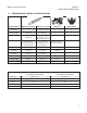
MODEL 396/396VP/397/398/398VP 1.2 SECTION 1.0 DESCRIPTION AND SPECIFICATIONS PERFORMANCE & PHYSICAL SPECIFICATIONS SPECIFICATIONS MODELS 396 &396VP MODELS 398 & 398VP MODEL 397 QUIK-LOC KIT Measurements and Ranges pH: 0-14 pH: 0-14 ORP: -1500 to 1500 mv pH: 0-14 — Available pH ACCUGLASSTypes GPHT hemi bulb or GPLR flat bulb GPHT hemi bulb or GPLR flat bulb GPHT hemi bulb — Wetted Materials 316 SST, Polypropylene, EPDM, glass Process Connection None, use 1 in.
MODEL 396/396VP/397/398/398VP SECTION 1.0 DESCRIPTION AND SPECIFICATIONS 1.3 ORDERING INFORMATION The Model 396 pH Sensor features your selection of glass electrode type, either the standard hemi bulb or the optional flat glass electrode combined with the coating resistant, polypropylene reference with gel filled electrolyte. The sensor is housed in a stainless steel body and is used with a 1 in. MNPT threaded process connector suitable for insertion, submersion, or flow through installations.
MODEL 396/396VP/397/398/398VP SECTION 1.0 DESCRIPTION AND SPECIFICATIONS The Model 398 Sensor, housed in a titanium tube and made with a Tefzel reference junction, can be used with a 1 inch MNPT process connector (purchased separately). The sensor is available with a hemi bulb glass pH electrode or a platinum and glass ORP electrode and with Pt100 or 3K temperature compensation. The 398 is provided with a standard 15 ft cable.
MODEL 396/396VP/397/398/398VP SECTION 1.0 DESCRIPTION AND SPECIFICATIONS The TUpH Model 397 pH Sensor is housed in a polypropylene body and is designed to be used with the Quik-Loc Kit. The sensor includes a large general purpose (GPHT) glass pH electrode and a large area polypropylene reference junction with gel filled reference electrolyte. The Model 397 is available without an integral preamplifier only and 15 ft (4.6 m) of cable.
MODEL 396/396VP/397/398/398VP SECTION 1.0 DESCRIPTION AND SPECIFICATIONS FOR FIRST TIME 396, 396VP, 398, AND 398VP INSTALLATIONS, ROSEMOUNT ANALYTICAL RECOMMENDS USING THE FOLLOWING GUIDE: 1. Process Connector Accessories (required for all first time installations with 1-inch process connection threads) Choose one: PN 23166-00, 316 SST, 1 in. x 1 in. NPT process connector, with EPDM o-ring PN 23166-01, Titanium, 1 in. x 1 in. NPT process connector, with EPDM o-ring PN 9510066, Nylon, 1 in. x 1 in.
MODEL 396/396VP/397/398/398VP SECTION 1.0 DESCRIPTION AND SPECIFICATIONS ADDITIONAL ACCESSORIES FOR MODEL 396, 396VP, 398 AND 398VP TUpH SENSORS PART NUMBER 33046-00 DESCRIPTION Ferrule 1 in., split 316 SS 33211-00 Adapter retrofit for PN 915240-04 9550167 EPDM O-ring for process connector (PN 23166-00) Ferrule, 1 in. Teflon1 9310100 9310096 9550167 Nut, Swage, 1 in. stainless steel O-ring, 2-214 EPDM 1 Teflon is a registered trademark of E.I. du Pont de Nemours & Co.
MODEL 396/396VP/397/398/398VP SECTION 2.0 INSTALLATION SECTION 2.0 INSTALLATION 2.1 UNPACKING AND INSPECTION. Inspect the outside of the carton for any damage. If damage is detected, contact the carrier immediately. Inspect the instrument and hardware. Make sure all the items in the packing list are present and in good condition. Notify the factory if any part is missing. If the sensor appears to be in satisfactory condition, proceed to Section 2.2, Mounting.
MODEL 396/396VP/397/398/398VP Wrap the pipe threads of the Twin-Kam Kamloc coupler with Teflon tape before placing it into the process pipe. The coupler can be connected to any 1 in. process connection and must be mounted within 80° of vertical, with the electrode facing down. Once the coupler is in place, the adapter should be positioned onto the back end of the sensor.
MODEL 396/396VP/397/398/398VP SECTION 2.0 INSTALLATION MILLIMETER INCH DWG. NO. 40039601 REV. J FIGURE 2-2.
MODEL 396/396VP/397/398/398VP SECTION 2.0 INSTALLATION INCH MILLIMETER Metal Process Connector PN 23166-xx (xx = 00 for 316 SST and xx = 01 for titanium) can be used for insertion or submersion mounting of Models 396VP or 398VP sensors in 1-inch fittings. The metal process connector gives the sensor various insertions depths, depending on where the user locates the compression fitting. Also the threads can be switched to face the cable end of the sensor for connection to submersion pipes. FIGURE 2-3.
MODEL 396/396VP/397/398/398VP SECTION 2.0 INSTALLATION MILLIMETER INCH P.N. 23166-00, 23166-01, OR 9510066 DWG. NO. REV. 40039603 C DWG. NO. 40039604 DWG. NO. 40039602 REV. D REV. D FIGURE 2-4. Submersion Installations for Models 396, 396VP, 398, and 398VP.
MODEL 396/396VP/397/398/398VP SECTION 2.0 INSTALLATION MILLIMETER INCH DWG. NO. 40039702 REV. C NOTE: The EP gasket (see drawing #40039702) provided with the coupler should be periodically inspected. If gasket shows signs of corrosion, replacement will be necessary to ensure a proper and secure seal between the coupler and adapter. DWG. NO. 40039704 REV. B DWG. NO. 40039701 FIGURE 2-5. Dimensional Drawings For Model 397 in the Quik-Loc Unit 14 REV.
MODEL 396/396VP/397/398/398VP DWG. NO. SECTION 2.0 INSTALLATION REV. 40039703 B FIGURE 2-6. Recommended Flow-Through and Insertion Installation For Model 397 2.3 ELECTRICAL INSTALLATION. The Models 396, 396VP, 397, 398, and 398VP are for use with a remote preamplifier. Each sensor comes with either a special 15 ft low noise coax cable or a Variopol (VP) connector, which is used with a mating Variopol cable.
MODEL 396/396VP/397/398/398VP SECTION 2.0 INSTALLATION DWG. NO. REV. 40039610 DWG. NO. 40039706 D REV. B FIGURE 2-9. Wiring Details For Model 396-54 (50), 397-54 (50), and 398-54 (50).
MODEL 396/396VP/397/398/398VP SECTION 2.0 INSTALLATION MILLIMETER INCH DWG. NO. REV. 40038920 G FIGURE 2-10. Wiring Details for Model 396-54, 397-54, and 398-54 (Pt-100 RTD). For Use With Junction Box (PN 23555-00) and Remote Preamplifier.
MODEL 396/396VP/397/398/398VP SECTION 2.0 INSTALLATION DWG. NO. 40039607 FIGURE 2-11. Wiring Details For Models 396, 397, and 398. For Use With Model 1181 pH. 18 REV.
MODEL 396/396VP/397/398/398VP SECTION 2.0 INSTALLATION MILLIMETER INCH DWG. NO. 40039606 REV. D FIGURE 2-12. Wiring Details For Models 396-54, 397-54, and 398-54.
MODEL 396/396VP/397/398/398VP SECTION 2.0 INSTALLATION MILLIMETER INCH DWG. NO. 40039608 FIGURE 2-13. Wiring Details For Models 396-54, 397-54, and 398-54. For Use With Models 2081 pH-05 and 1054 pH-54 20 REV.
MODEL 396/396VP/397/398/398VP SECTION 2.0 INSTALLATION MILLIMETER INCH DWG. NO. REV. 40039605 F FIGURE 2-14. Wiring Details For Models 396-54 , 397-54, and 398-54. For Use With Models 54, 54e, 81, 3081, 4081, and 5081.
MODEL 396/396VP/397/398/398VP SECTION 2.0 INSTALLATION MILLIMETER INCH DWG. NO. 40039611 FIGURE 2-15. Wiring Details For Models 396-54 , 397-54, and 398-54. For Use With SoluComp Model SCL-P-014. 22 REV.
MODEL 396/396VP/397/398/398VP SECTION 2.0 INSTALLATION FIGURE 2-16. Wiring Models 396-54, 397-54, and 398-54 to Model 2700 Preamplifier (PN 23054-03). FIGURE 2-17. Wiring Models 396-( )-54-62-(71), 397-02-10-54-62, and 398-( )-54-62 to Model 1055-01-10-22-32 FIGURE 2-18.
MODEL 396/396VP/397/398/398VP SECTION 2.0 INSTALLATION See below for wire functions for Models 396VP and 398VP. The Variopol connector cable part numbers are PN 2364506 (with BNC) and PN 23645-07. FIGURE 2-19. Wire Functions and Pin Connections for Variopol connector cable PN 23645-06 (with BNC) FIGURE 2-21. Wiring Model 396VP and 398VP to Model 81 24 PN 23645-07 FIGURE 2-20. Wiring Model 396VP and 398VP to Model 81 through a Remote Junction Box FIGURE 2-22.
MODEL 396/396VP/397/398/398VP SECTION 2.0 INSTALLATION FIGURE 2-24. Wiring Model 396VP and 398VP to Model 2081 FIGURE 2-25. Wiring Model 396VP and 398VP to Model 3081 and 4081 FIGURE 2-23. Wiring Model 396VP and 398VP to Model 1181, 1050/1060, and 1003/1023 through a Remote Junction Box FIGURE 2-26. Wiring Model 396VP and 398VP to Model 2081 through a Remote Junction Box FIGURE 2-27.
MODEL 396/396VP/397/398/398VP 26 SECTION 2.0 INSTALLATION FIGURE 2-28. Wiring Model 396VP and 398VP to Model 1054 FIGURE 2-29. Wiring Model 396VP and 398VP to Models 1054A, 1054B, and 2054 FIGURE 2-30. Wiring Model 396VP and 398VP to Model 1054 through a Remote Junction Box FIGURE 2-31.
MODEL 396/396VP/397/398/398VP SECTION 2.0 INSTALLATION FIGURE 2-32. Wiring Model 396VP and 398VP to Models 54 and 54e through a Remote Junction Box FIGURE 2-33. Wiring Model 396VP/398VP to Models 54/54e FIGURE 2-34. Wiring Model 396VP and 398VP to Model SCL-(P/Q) FIGURE 2-35.
MODEL 396/396VP/397/398/398VP FIGURE 2-36. Wiring Model 396VP-54 to Model 1055-22-32 28 SECTION 2.
MODEL 396/396VP/397/398/398VP SECTION 2.0 INSTALLATION FIGURE 2-37. Wiring Models 396-54-6, 397-54-62, & 398-54-62 to Model Xmt-P-XX-10 XMT -P XX -10 396VP 398VP FIGURE 2-38.
MODEL 396/396VP/397/398/398VP SECTION 2.0 INSTALLATION FIGURE 2-39. Wiring Models 396/397/398 to Model 5081-P 1055 -01 -10 -22 -32 Model 396-54-62 Model 398-54-62 FIGURE 2-40.
MODEL 396/396VP/397/398/398VP SECTION 3.0 START UP AND CALIBRATION SECTION 3.0 START UP AND CALIBRATION 3.1 SENSOR PREPARATION. Shake down the sensor to remove any air bubbles that may be present at the tip of the pH glass bulb. In most cases, the pH sensor can simply be installed as shipped and readings with an accuracy of ±0.6 pH may be obtained. To obtain greater accuracy or to verify proper operation, the sensor must be calibrated as a loop with its compatible analyzer or transmitter. 3.
MODEL 396/396VP/397/398/398VP SECTION 4.0 MAINTENANCE SECTION 4.0 MAINTENANCE 4.0 MAINTENANCE. The Model 396, 396VP, 397, 398, and 398VP Sensors are disposable type sensors and therefore require minimum maintenance. Every sensor should be kept clean and free of debris and sediment at all times. The frequency of cleaning by wiping or brushing with a soft cloth or brush is determined by the nature of the solution being measured.
MODEL 396/396VP/397/398/398VP SECTION 5.0 TROUBLESHOOTING SECTION 5.0 TROUBLESHOOTING TABLE 5-1. Troubleshooting Trouble Probable Cause Remedy Meter reads off scale. (Display reads overrange.) T.C. element shorted. Check T.C. element as instructed in Section 4.2 and replace sensor if defective. Sensor not in process or sample stream is low. Make sure sensor is in process with sufficient sample stream (refer to Section 2.0 for installation details). Open glass electrode. Replace sensor.
MODEL 396/396VP/397/398/398VP SECTION 6.0 RETURN OF MATERIAL SECTION 6.0 RETURN OF MATERIAL 6.1 GENERAL. 6.3 NON-WARRANTY REPAIR. To expedite the repair and return of instruments, proper communication between the customer and the factory is important. Before returning a product for repair, call 1-949-757-8500 for a Return Materials Authorization (RMA) number. The following is the procedure for returning for repair instruments that are no longer under warranty: 1.
WARRANTY Seller warrants that the firmware will execute the programming instructions provided by Seller, and that the Goods manufactured or Services provided by Seller will be free from defects in materials or workmanship under normal use and care until the expiration of the applicable warranty period. Goods are warranted for twelve (12) months from the date of initial installation or eighteen (18) months from the date of shipment by Seller, whichever period expires first.
The right people, the right answers, right now. ON-LINE ORDERING NOW AVAILABLE ON OUR WEB SITE http://www.raihome.com Specifications subject to change without notice. 8 Credit Cards for U.S. Purchases Only. Emerson Process Management 2400 Barranca Parkway Irvine, CA 92606 USA Tel: (949) 757-8500 Fax: (949) 474-7250 http://www.raihome.com © Rosemount Analytical Inc.