POWER AVAILABILITY 3U MP2-220N POD™ USER MANUAL Power Output Distribution 208 Volt 16 Amp
TABLE OF CONTENTS IMPORTANT SAFETY INSTRUCTIONS . . . . . . . . . . . . . . . . . . . . . . . . . . . . . . . . . . . . . . . . . . . . . . . .1 GLOSSARY OF SYMBOLS . . . . . . . . . . . . . . . . . . . . . . . . . . . . . . . . . . . . . . . . . . . . . . . . . . . . . . . .2 1.0 INTRODUCTION AND SYSTEM DESCRIPTION . . . . . . . . . . . . . . . . . . . . . . . . . . . . . . . . . . . . .3 1.1 System Description. . . . . . . . . . . . . . . . . . . . . . . . . . . . . . . . . . . . . . . . . . . . . . .
ii
IMPORTANT SAFETY INSTRUCTIONS SAVE THESE INSTRUCTIONS ! WARNING Do not attempt to service this product yourself. Opening or removing the cover may expose you to dangerous voltages, even when the AC cord is disconnected from the electrical socket. Refer all servicing to qualified service personnel. This manual contains important instructions that should be followed during installation and operation of the MP2-220N POD™.
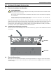
GLOSSARY OF SYMBOLS Equipment grounding conductor Bonded to ground Electric phase Indicates AC input Indicates AC output Indicates caution followed by important instructions 2
Introduction and System Description 1.0 INTRODUCTION AND SYSTEM DESCRIPTION Congratulations on your choice of the Liebert MP2-220N POD™ (3U POD). The 3U POD provides maintenance bypass capability as well as power output distribution. The 3U POD can be used on UPSs in the rack mount or tower configuration. The 3U POD provides an isolated path of power for your UPS system for preventive maintenance or service. As shipped, cords and receptacles provide ready to use UTILITY and LOAD connections.
Rack Mount Installation 2.0 RACK MOUNT INSTALLATION 1. Rack mount installation of the 3U POD is possible with the use of the rack mounting brackets (shipped with the 3U POD). See Figure 4. 2. The rack mounting brackets allow you to rack mount the 3U POD in a 19" enclosure (23" to 19" rack adapters would have to be purchased separately if you are using our 23" Foundation or equivalent cabinet). 3.
Installation and Electrical Connections 3.0 INSTALLATION AND ELECTRICAL CONNECTIONS Unpack the 3U POD carefully, noting the packing method. Retain the box and packing material for possible future shipments. Visually inspect the 3U POD for freight damage. Report damage to the carrier and your local dealer, Liebert representative or the Liebert Worldwide Support Group. 3.
Alternate Hardwire Installation 4.0 ALTERNATE HARDWIRE INSTALLATION 4.1 Electrical Installation Considerations ! WARNING This unit must be installed by competent electrical personnel and wired in accordance with local/national electrical codes. Review this entire manual and the installation instructions in this section before beginning the installation. Before installing, open all branch circuit power at the nearest disconnect, turn the UPS off, and disconnect all cords to and from the UPS.
Alternate Hardwire Installation 4.3 Conversion From Cord-Receptacle to Hardwire Two wiring access panels on the front of the 3U POD allow access to the wiring compartments. Each access door is retained using four Phillips head screws. 1. Remove the eight Phillips head screws from the wiring access panels on the front of the unit. Save the screws. 2. Holding the panels aside, disconnect the three wires that connect each panel to the internal terminal block. Remove the panels.
Indicator Lamps 5.0 INDICATOR LAMPS 5.1 UTILITY Indicator Lamp This amber lamp is illuminated when utility power is present (see Figure 5). It signals that you may transfer the loads to maintenance bypass (UTILITY mode) operation via the rotary switch. During a utility power outage, this lamp will be off and the UPS will supply battery back-up power to the connected loads. 5.2 UPS Indicator Lamp This green lamp is illuminated when there is output power available from the UPS (see Figure 5).
Operation 6.0 OPERATION 6.1 Transfer to Maintenance Bypass To transfer to maintenance bypass (utility) from UPS, use the following steps: 1. Ensure the UTILITY lamp (amber) is illuminated. If the lamp is not illuminated, refer to 7.0 Troubleshooting. 2. Transfer the rotary switch from UPS to UTILITY, provided the UTILITY lamp is illuminated on the 3U POD. 3. Turn the UPS off. 4. Disconnect the two cables connecting the UPS to the 3U POD. 5. You may now service the UPS. 6.
Troubleshooting 7.0 TROUBLESHOOTING Problem Cause Solution Utility not present. Call qualified service personnel to restore power. Utility Branch Circuit Breaker may be open. Verify that the branch circuit breaker is closed. 3U POD input power not connected to UTILITY. Refer to the 3U POD installation instructions in this manual: 2.0 - Rack Mount Installation 3.0 - Installation and Electrical Connections 4.0 - Alternate Hardwire Installation UPS output power not present. Turn on the UPS.
Specifications 8.0 SPECIFICATIONS Transfer Time (to and from maintenance bypass) < 6 milliseconds Operating Ambient Temperature 32°F to 104°F (0°C to +40°C) Storage Ambient Temperature -4°F to 140°F (-20°C to +60°C) Dimensions with brackets W x D x H: in. (mm) 19.0 x 5.24 x 5.24 (482.
Specifications 12
POWER AVAILABILITY 3U MP2-220N POD™ USER MANUAL The Company Behind the Products With over a million installations around the globe, Liebert is the world leader in computer protection systems.