
Switch User Manual


INSTALLATION (continued)
1 --- 3
Functional Test
The Functional Test consists of three checks: manua l
operation, voltage checks, and electrical operation.
NOTICE
Do these checks in the order presented to avoid
damaging the automatic transfer switch.
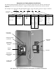
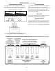
Read all instructions on the Wiring Diagram and labels
affixed to the automatic transfer switch. Note the
control features that are provided and review their
operation before proceeding.
1 – Manual Operation Test
A detachab l e manual operator handle is prov ided on the
Trans fer Switc h for maintenanc e purposes only
.Manual
operation of the transfer switch should be checked
before it is energized (operated electrically).
Do not manually operate the transfer switch until
both power sources are disconnected: open
both circuit breakers.
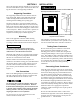
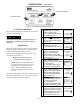
1. Insert the maintenance handle into the hole in the
shaft, left side of the operator.
2. Move the maintenanc e handle as show n to manu ally
operate the transfer switch. The switch should operate
smoothl y without any binding. If it does not, check for
shipping damage or construction debris.
3. Return the transfer switc h to the N (normal) position.
4. R emove the maintenance handle and store it on the
trans fer switc h in the pl ac e pro vid ed .
NOTICE
Verify that the maintenance handle has been
removed before proceeding!
Now continue to 2–VoltageCheckson next page.
maintenance
handle
shaft
hole
Figure 1-4. Removable maintenance handle on
260 an d 400 ampere transfer switches.