
User Guide


IM584000300 Installation Instructions
Issue AB, April 3, 2013 Spec. No. 584000300 (Model 4015-X003)
Page 32 Chapter 3. Making Electrical Connections
This document is property of Emerson Network Power, Energy Systems, North America, Inc. and contains confidential and proprietary information owned by Emerson Network Power, Energy
Systems, North America, Inc. Any copying, use, or disclosure of it without the written permission of Emerson Network Power, Energy Systems, North America, Inc. is strictly prohibited.
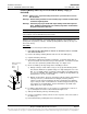
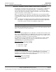
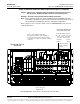
Figure 3-12
Installing Battery Sub-Trays in List 91 and 92 Battery Tray(s)
Battery Sub-Trays
Battery Tray
Battery Tray
Battery
Retaining
Bracket
On the sub-trays that hold five (5)
batteries, one battery string cable
is disconnected and sleeved at the
factory. Locate this lead and connect
it to the open battery terminal in that tray.
Battery tray output cables
not shown for clarity.
Note: Battery tray must be
installed in rack before
installing batteries.
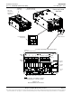
Rear
Battery Sub-Tray Connector
Battery wiring connectorized
for easy installation.
If a battery temperature probe
is to be used, it is recommended
to secure it on top of a battery
block near this location.
Battery Tray Connector
X