
Installation Manual


Installation, Operation and Maintenance Manual IO-70104 Rev 2, 6/2014
CAUTION — For proper and safe operation, neutral and ground
MUST be reliably connected. Failure to operate this unit from a
solidly grounded power source of the proper configuration will
reduce or impede operation, and may result in unit failure.
ATTENTION - Pour un fonctionnement correct et sûr, le neutre et la mise à la terre doit être
connectés de manière fiable. Défaut de faire fonctionner cet appareil à partir d'une source
d'alimentation solidement mise à la terre va réduire ou même empêcher le fonctionnement
correct et peut entraîner une défaillance de l'unité.
Applying Power — Apply power to the SPD and assure status indications are normal. Under
normal conditions, the green “OK” LED is illuminated and the red “REPLACE” LED is OFF. If
normal status indication does not exist, see “TROUBLESHOOTING”.
PRODUCT RATINGS AND LIMITATIONS
Voltage Protection Rating – To obtain the voltage protection ratings (VPRs), as obtained by
Underwriters Laboratories, Incorporated, in accordance with the Standard for Safety, Surge
Protective Devices (SPDs), Standard 1449 Third Edition, released 2009, marked on this product,
the #12 AWG wire supplied must be utilized to connect the 420/425 SPD to your facilities’
power grid. Connections made with conductors other than #12 AWG may result in different
VPRs.
Circuit Ampacity Limitations – This device has been investigated by Underwriters
Laboratories, Incorporated to withstand, without exposing live circuits or components on
power sources, a voltage of two times (2x) the device ratings, and fault currents of up to
200,000 AIC, as described in the Standard for Safety, Surge Protective Devices (SPDs), Standard
1449, Third Edition, released 2009.
TROUBLESHOOTING
If any of the diagnostic indicators indicates a problem (i.e. red LED ON, and/or green LED OUT), check
all connections and voltages to the unit. If all connections are reliable, and proper voltages are
supplied to the unit, call Emerson Network Power Surge Protection, Inc at 607-721-8840.
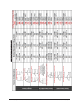
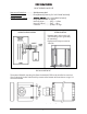
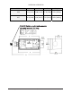
MODEL NUMBER CONFIGURATION
Model #: _ _ _ _ _ _ _ _ _ _ _ _ _
(11)
Enclosure
J = NEMA Type 4X
(plastic)
(12) UL 1449 Type
0 = No UL
1 = Type 1, 20kA
2 = Type 2, 20kA
(13) MOV Option
S = Standard
Q = High Rated
(8) Modes of Protection
A = All Modes of
Protection .. (100kA Per Phase)
B = L-N & N-G ... (50kA Per Phase)
E = L-L ............... (50kA Per Phase)
F = L-N .............. (50kA Per Phase)
(9) Connection Type
W = Wire Leads
(10) Monitoring Options
R = LED/Relay
A = LED/Alarm/Relay
(1-3) Series
420 = Non-Modular;
Reduced Mode
425 = Non-Modular; All
Mode
(4-5) Configuration &
Voltage
See Chart on Next Page
(6-7) Surge Rating Per Mode
05 = 50kA
1 2 3 4 5 6 7 8 9 10 11 12 13
3