
Two-Wire Toroidal Conductivity Transmitter Instruction Manual

84
MODEL 5081-T SECTION 10.0
DIAGNOSIS AND TROUBLESHOOTING
10.8.3 CAL Error
At the end of the calibration step, the transmitter calculates the sensitivity in nA/ppm. If the sensitivity is outside the range
normally expected, the transmitter displays the CAL Error message and the transmitter does not update the calibration.
For assistance, refer to the troubleshooting section specific for the sensor.
10.8.4 nEEd 0 CAL
nEEd 0 CAL means that the concentration of the analyte is too negative.
1. Check the zero current (go to 0 CurrEnt under the diagnostic menu). If the zero current is appreciably greater than the
measurement current, the nEEd 0 CAL warning will appear.
2. Verify that the zero current is close to the value given in the calibration section for the analyte being determined.
3. Rezero the sensor. Refer to the calibration and troubleshooting sections for the sensor for more information.
10.8.5 rtd FAIL, TEMP HI, and TEMP LO
These messages usually mean that the RTD is open or shorted or there is an open or short in the connecting wiring.
1. Verify all wiring connections, including wiring in a junction box if one is being used.
2. Disconnect the RTD IN, RTD SENSE, and RTD RETURN leads or the thermistor leads at the transmitter. Be sure to
note the color of the wire and where it was attached. Measure the resistance between the RTD IN and RETURN leads.
For a thermistor, measure the resistance between the two leads. The resistance should be close to the value in the
table in Section 10.6. If the temperature element is open or shorted, replace the sensor. In the meantime, use manu-
al temperature compensation.
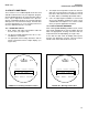
10.8.6 SenSE OPEn
Most Rosemount Analytical sensors use a Pt100 or Pt1000 in a three-wire configuration. The in and return leads connect
the RTD to the measuring circuit in the analyzer. A third wire, called the sense line, is connected to the return lead. The
sense line allows the analyzer to correct for the resistance of the in and return leads and to correct for changes in lead wire
resistance with changes in ambient temperature.
1. Verify all wiring connections, including wiring in a junction box if one is being used.
2. Disconnect the RTD SENSE and RTD RETURN wires. Measure the resistance between the leads. It should be less
than 5 Ω. If the sense line is open, replace the sensor as soon as possible.
3. The transmitter can be operated with the sense line open. The measurement will be less accurate because the
transmitter can no longer compensate for lead wire resistance. However, if the sensor is to be used at approximately
constant ambient temperature, the lead wire resistance error can be eliminated by calibrating the sensor at the
measurement temperature. Errors caused by changes in ambient temperature cannot be eliminated. To make the
error message disappear, connect the RTD SENSE and RETURN terminals with a jumper.