
Installation Manual
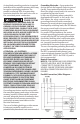

Installation, Operation and Maintenance Manual IO-70103 Rev 2, 1/2015
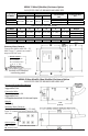
MONITORING FEATURES
External Status Indicators (Standard) —
These indicators provide a summary of the
status of the surge SPD module. For normal
conditions, the green “OK” LED is illuminated
and the red “Service” LED is extinguished. If
the surge SPD module requires replacement,
the green “OK” LED is turned off and the red
“Service” LED illuminated.
Audible Alarm (Standard/Optional) — If the
surge SPD module requires replacement, an
audible alarm may be activated to draw
attention to the fact that repair service is
required to restore the system to normal
operation. An audible alarm disable is
provided to silence the alarm. The system will
automatically reset itself after repair. The
audible alarm switch and “Service” LED can be
tested by activating the “Test” switch on the
system monitor panel.
Summary Alarm Contact
(Standard/Optional) — One or two sets of
summary alarm Form C relay contacts (N.O.
and N.C.) are provided for remote indication
of the failed surge SPD module. Contacts are
rated 5 amps at 250 VAC maximum with a
power factor of 1.0. Access to the contacts is
provided via contact terminals located inside
of the unit’s cover.
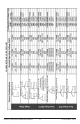
Surge Counter (Optional) — The surge
counter is provided for transient voltage
surge monitoring. The counter totalizes line
surges monitored since the last time the
counter was reset. The circuit counts all
surges that deviate from the line sine wave.
The factory setting is 30% over nominal line
voltage. Other settings include 50%, 70%, and
100%.
Advanced Transient Detection System
(Optional) —
A web-based monitoring device
allowing real time power quality measurements,
logged events, statistical summaries and premium
power protection. Understanding the severity,
type and timing of the event allows you to analyze
trends and ultimately better manage your
electrical system. (See SL-70109 for further
information)
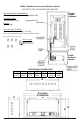
TROUBLESHOOTING/SERVICING
MAINTENANCE
Troubleshooting —
If status failure indication occurs or summary
alarm contacts have changed state, a
qualified electrician shall first determine if the
systems voltage and proper phasing exists.
If the SPD remains in an alarm condition
once the electrician is satisfied that the
electrical system and its connections are
normal, the unit should be repaired.
At this point consult the factory, having
available the following information:
Model number and serial number detailed
on the units’ data label (located on the
front of the enclosure).
Nature of problem – (including condition of
all status indicators and alarms).
Servicing —
The Emerson Network Power 510 Series
comes with a ten year warranty. For
servicing assistance, contact your local Sales
Representative or Emerson Network Power,
Surge Protection at 800-288-6169 or 607-
721-8840.
DANGER! ONLY
QUALIFIED
PERSONNEL SHOULD INSTALL OR SERVICE
THIS SYSTEM. ELECTRICAL SAFETY PRE-
CAUTIONS MUST BE FOLLOWED WHEN
INSTALLING OR SERVICING THIS
EQUIPMENT. TO PREVENT RISK OF
ELECTRICAL SHOCK, TURN OFF AND LOCK
OUT ALL POWER SOURCES TO THE UNIT
BEFORE MAKING ELECTRICAL
CONNECTIONS OR SERVICING.
DANGER! SEULEMENT LE PERSONNEL
QUALIFIÉ DOIT INSTALLER OU MAINTENIR
CE SYSTÈME. DES PRÉCAUTIONS DE
SÉCURITÉ EN ÉLECTRICITÉ DOIVENT ÊTRE
SUIVIS LORS DE L'INSTALLATION OU DE LA
MAINTENANCE DE CET EQUIPEMENT.
POUR EVITER TOUT RISQUE DE CHOC
ÉLECTRIQUE, DÉBRANCHEZ ET VEROUILLER
TOUTES LES SOURCES D’ ALIMENTATION DE
CET EQUIPEMENT AVANT DE LE BRANCHER
OU LE MAINTENIR.
(continued)