
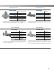
Data Sheet
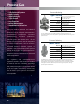


Regulator Tips
22
All regulators should be installed and used in accordance with federal, state, and local codes and regulations.
PRESSURE
• Adequate overpressure protection should be installed
to protect the regulator from overpressure. Adequate
overpressure protection should also be installed to
protect all downstream equipment in the event of
regulator failure.
• Downstream pressures significantly higher than the
regulator’s pressure setting may damage soft seats and
other internal parts.
• When a regulator appears unable to pass the published
flow rate, be sure to check the inlet pressure measured
at the regulator body inlet connection. Piping up to
and away from regulators can cause significant flowing
pressure losses.
• When adjusting setpoint, the regulator should be flowing
at least five percent of the normal operating flow.
• Droop is the reduction of outlet pressure experienced by
pressure reducing regulators as the flow rate increases. It
is stated as a percent, in inches of water column (mbar)
or in pounds per square inch (bar) and indicates the
difference between the outlet pressure setting made
at low flow rates and the actual outlet pressure at the
published maximum flow rate. Droop is also called offset
or proportional band.
• Downstream pressure always changes to some extent
when inlet pressure changes.
• A disk with a cookie cut appearance probably means you
had an overpressure situation. Thus, investigate further.
SPEED OF RESPONSE AND ACCURACY
• If two or more available springs have published pressure
ranges that include the desired pressure setting, use the
spring with the lower range for better accuracy.
• Direct-operated regulators generally have faster response
to quick flow changes than pilot-operated regulators.
• Speed of regulator response, in order:
- Direct-operated
- Two-path pilot-operated
- Unloading pilot-operated
- Control valve
Note: Although direct-operated regulators give the fastest
response, all types provide quick response.
• The full advertised range of a spring can be utilized
without sacrificing performance or spring life.
SIZING
• The recommended selection for orifice diameters is the
smallest orifice that will handle the flow.
• Regulator body size should never be larger than the pipe
size. In many cases, the regulator body is one size smaller
than the pipe size.
• Do not oversize regulators. Pick the smallest orifice
size or regulator that will work. Keep in mind when
sizing a station that most restricted trims that do not
reduce the main port size do not help with improved low
flow control.
• Most soft-seated regulators will maintain the pressure
within reasonable limits down to zero flow. Therefore,
a regulator sized for a high flow rate will usually have
a turndown ratio sufficient to handle pilot-light loads
during off cycles.
• Do not undersize the monitor set. It is important to realize
that the monitor regulator, even though it is wide-open,
will require pressure drop for flow. Using two identical
regulators in a monitor set will yield approximately
70 percent of the capacity of a single regulator.
TEMPERATURE
• Most regulators shown in this handbook are generally
suitable for temperatures to 180°F / 82°C. With high
temperature Fluorocarbon (FKM) (if available), the
regulators can be used for temperatures to 300°F /
149°C. Check the temperature capabilities to determine
materials and temperature ranges available. Use stainless
steel diaphragms and seats for higher temperatures, such
as steam service.
• For every 15 psid / 1.0 bar, differential pressure differential
across the regulator, expect approximately one degree
drop in gas temperature due to the natural refrigeration
effect. Freezing is often a problem when the ambient
temperature is between 30°F / -1°C and 45°F / 7°C.