
Service manual

Emerson
Radio
VIDEO
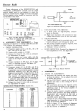
I-F
ALIGNMENT: (Table
VI).
STEP
1
2
3
4
5
SIGNAI
GENER
CONNECTION
Lightly
couple
marker
gen.
to
pin
1 of
V3:
Sweep
gen. from
pin
1 to
chassis,
:hrough
.001 mfd.
Connect marker
and
sweep
gener-
ators
to pin 1
of
V2,
through
.001 mfd.
Low
side
to
chassis.
Sweep
generator
coupled
to
con-
verter
(V27)
in-
put,
using three
turn loop slipped
over
tube.
Marker
gen.
in
parallel.
Low
side
to
chassis.
TJ
»
Connect
AGC
ATOR
INPUT
FREQUENCY
Sweep-
23.5
MC
(10
MC.
sweep)
Marker-25.75
MC.
Sweep
-23.
SMC.
(10
MC.
sweep)
Marker-25.25
MC.
Sweep-
23.5
MC.
(
10
MC.
sweep)
Marker-25.75
MC.
Sweep
-23.
SMC.
(10
MC.
sweep)
Markers-
22.8
and
21.25
MC.
Sweep
-
23.5
MC
bias
battery
as
(
10
MC.
sweep)
indicated
above.
!
Markers-
25.75
MC.
and
22.25
MC.
MEASURING
INSTRUMENT
Connect vertical
input
of
scope
through
10K
re-
sistor
to
junction
of
Ll,
R16,
and
C16.
Low
side
to
chassis.
»
Connect scope
through
detector
network
to pin 1
of
V2. Low
side
to
chassis.
Connect scope
through
detector
network
to pin 1
of
V3. Low
side
to
chassis.
Connect scope
through
10K
re-
sistor
to
junction
of
Ll, R16 and
C16.
Low
side
to
ciiassis.
ADJUST
T4
(Top
and
bottom)
T3
Tl
(L7
and
L9)
T2
(Top
and
bottom)
T2,
T3
PROCEDURE
Set
marker
as
shown
on
response curve; marker
should
be 10%
down.
Ad-
just
sweep generator
in-
put
to
produce
one
volt
at
junction
of Ll,
R16,
and
C16.
Set
25.25
MC.
marker
as
shown
on
response curve.
Set
marker
as
shown
on
response curve.
Adjust
primary
of T2
(top)
to
position 22.8
MC.
marker; adjust
T2
trap (bottom)
to
position
21.25
MC.
marker.
Adjust
T2
(top)
and T3
to
give overall response
shown.
T2
(tor>)
adiusts
bandwidth;
T3
positions
video carrier (25.75 MC.)
depending
on
accuracy
of
adjustment
of Tl
(25.75
MC.
marker).
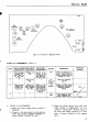
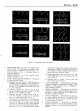
RESPONSE
CURVES
25.75MC.
MARKER
^t"^"
*~\
\
\
\
BAND
WIDTH
\
4.7
MC
\
25.2SMC.
/
XI
/
\
\
\N
J25.7SMC.
\I
MARKER
\
\
\
BAND
WIDTH
\
4
SMC
\
/JlZZ.BO
MC.
/l\R
y
\
Vm
/
T^K
s~*
—
•"•>
/
\y
\
2 2.2
SMC.
MARKER/!
IMARKER
/
BANDWIDTH
\
3.5
MC
\O
I-F
ALIGNMENT:
(Table
VI).
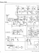
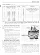
c.
TUNER
ALIGNMENT:
1) Set fine
tuning control
to
center
of
rotation.
Retain
tbis
setting
or
entire
r-f
alignment.
2)
Retain control settings previously
used.
3)
Couple marker generator
in
parallel
with
sweep
generator.
4) Use 10
inc.
sweep
lor
sweep
generator.
Couple
generator
to
antenna terminals
of
receiver.
If
the
sweep
has a 50
ohm,
unbalanced output,
connect
to the
antenna terminals through
net-
work shown
in figure
5-5.
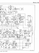
5)
Connect vertical input
of
scope
in
scries
with
10K
resistor
to
junction
of Ll,
R16,
and
C16.
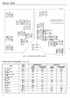
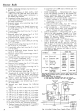
6)
Refer
to figure 5-8 for
tuner alignment points,
and figure
4-12
for the
tuner schematic.
7)
A14, A15,
A16 are
r-f
amplifier
and
converter
trimmers
and are
adjusted
on
Channel
12;
A13-A2
are
oscillator slugs
for the
correspond-
ing
channels.
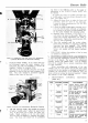
FIRST
I-F
TRANSFORMER
T-l
t-9
1
R^
AMPLIFIER
(SEC.)
*7
SAGS
.
R-F
AMP.
INPUT
TRIMMER
A-14
figure
?-8—Tuner
Alignment
Points
16