
Service manual

Emerson
Radio
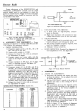
TUNER
ALIGNMENT:
(Table VII).
STEP
1
2
3
4
5
6
7
8
9
10
11
12
13
SIGNAL
GENERATOR
INPUT
SWEEP
GEN.
207.0
MC.
»
213.0
MC.
201.0
MC.
195.0
MC
189.0
MC.
183.0
MC.
177.0
MC.
85.0
MC.
79.0
MC.
69.0
MC.
63.0
MC.
57.0
MC.
MAR. GEN.
209.75
MC.
ft
215.75
MC.
203.75
MC.
197.75
MC.
191.75
MC.
185.75
MC.
179.75
MC.
87.75
MC.
81.75
MC.
71.75
MC.
65.75
MC.
59.75
MC.
CHANNEL
12
12
13
11
10
9
8
7
6
5
4
3
2
ADJUST
A12
A14,
A15,
A16
A13
All
A10
A9
A8
A7
A6
A5
A4
A3
A2
PROCEDURE
Adjust
for
placement
of
21.25
MC.
marker
as
per
overall
response
curve.
Adjust
shape
of
overall
response
curve
for
maximum
amplitude
and
bandwidth.
Adjust
as in
Step
I.
»
»>
»
»
»
j>
>»
»>
»
»
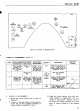
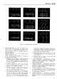
NOTE:
The r-f
response curve
of the
tuner,
on
each
channel
may be
observed
by
connecting
the
scope
in
series with
a 10K
resistor
to the
test point shown
in
figure 5-9.
The
curves
should
have maximum amplitude
and
flatness, consistent with
proper placement
of the
21.25
me.
marker
on the i-f
response curve.
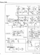
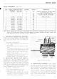
8.
VOLTAGE
AND
RESISTANCE
ANALYSIS—
Voltage
and
resistance readings
are
indicated
in figure
5-10,
to aid in
servicing
the
chassis.
The
diagram indi-
cates typical values
obtained
under
the
following
con-
ditions.
a.
ANALYSIS
CONDITIONS:
1)
Line voltage maintained
at 117
volts
for
volt-
age
readings.
2)
Measurements made with
voltohmyst
or
equiv-
alent.
3) All
voltage measurements
are in +
d.c. volts
and
resistance
in
ohms, unless otherwise noted.
4)
Socket
connections
are
shown
as
boUom
v'<"vs.
Measured values
are
from socket
pin to
B—,
unless
otherwise stated.
5)
Readings made
with
antenna disconnected,
no
signal
applied
and
controls
at
normal.
6)
Readings marked
* are
measured
to
ground.
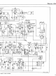
9.
DEFLECTION
CIRCUIT
WAVE FORMS
—
See figure
5-11.
The
sweep voltages produced
in the
horizontal
and
vertical sweep circuits
may be
used
in
locating
defects
in the
deflection section
of the
chassis.
Two
separate wave forms
are
shown
at
various test
points
up to the
output
of the
second sync
amplifier
(V6B),
as
both horizontal
and
vertical pulses
ar?
pres-
ent.
Different
sweep
frequencies
are
required
at the
scope
to
distinguish
between
the
sync pulses.
a.
ANALYSIS
CONDITIONS:
1)
Line voltage maintained
at 117
volts.
2)
Controls
at
normal
; no
signal
input.
3)
Peak-to-peak values indicated
may
vary
due
to
component tolerances
and
response
of
scope.
Readings
are
obtained
by
calibration
of
scope,
prior
to
observation
of
waveforms.
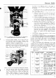
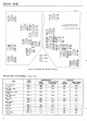
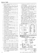
OSC.
AND
CONV
TEST
POINT
TRIMMER
»-!«
R-F
OUTPUT,
CONV.,
AND
OSC.
COILS
(L-S,L-4,L-5>
Figure
5-9—Side
View
Tuner
10.
PRODUCTION
CHANGES—Several
changes
have
been incorporated
in the
chassis used
in
Models
614, 637,
and
644, during production.
These
changes
may be
identified
by
code markings consisting
of a
tri-
angle
containing
a
particular number, stamped
at the
rear
of the
chassis. Presence
of a
particular marking
indicates
that
the
revisions described
have
been made
in
the
chassis.
The
various
revisions
are
summarized
below.
Unless otherwise noted,
the
changes have been
added
to all
subsequent models.
17