
Service manual


Emerson
Radio
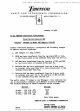
11.
SECONDARY
AREA
RECEPTION
—
Noise
conditions
in
secondary
areas
of
signal
reception
(fringe
areas),
or in
areas
where
noise
is
excessive
compared
to
signal
level,
give
rise
to
problems
of
sync
stability.
For
such
areas
only,
the
following simple
changes
should
be
made
in the
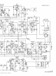
circuit. References
are
lo
the
schematic diagram.
a.
Remove
end of R8
connected
to
CIO
and the AGC
bus;
reconnect
to
chassis.
b.
Remove
end of R17
connected
to pin 7 of
V4;
re-
connect
to
junction
of
LI,
C16,
and
R16.
c.
Do not
make
this change
for
sets
operating
in
primary
signal
areas.
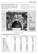
T-9-,
C-64-,
T-8
R-60
R-IOO
R-96
it
ii
n
n
Jl
R-62(B+,I50V)
R-6l(B-,-l9SV)
TUNER
V-Z9
C-66
T-12
L-12
C-4O(20OV)
C-42(I50V>
C-74(I96V)
0-21
(-I74V)
C-39(200V)
C-4KI80V)
C-S6(IOBV)
C-291-I96V)
VIO.
OET.
OUTPUT
(V-4)
AGC
BUS(-?..8V,
ANT.
SHORTED)
T-7
V-IO
V-9
C-80
R-94(VERT.
MOLD)
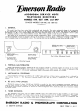
INDICATED
VOLTAGES
MEASURED
TO
CHASSIS
,
WITH
ALL
FRONT
CONTROLS
COUNTER-CLOCKWISE
AND
REAR
CONTROLS
NORMAL;
NO
SIGNAL
INPUT.
Figure
5-13—Bottom
View
of
Chassis
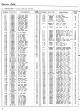
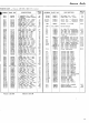
12.
CABINET
PARTS
LIST
(Models
614. 637. 644, 647).
ITEM
Cabinet
Cabinet
back
Safety
glass
Mule
Mask
extrusion
Panel gasket
Cabinet
feet
Selector
escutcheon
Bakehte
front
Knob
—
Fine
Tuning
Knob
—
Selector
Knob
—
Contrast
Knob
—
Brighntess
Knob
—
Vert. Hold
Knob
—
Off-
Volume
Knob
—
Hor. Hold
Spring
insert
—
1/4
shaft
Spring
insert
—
3/8
shaft
Spring
insert
—
3/16
shaft
PART
NO.
MODEL
614
140279
560097
635023
410805
520103
450044
45005
IS
450045
450045
450046S
450041S
450O46S
587011
587012
587013
MODEL
637
140276
560103
635020
445008
450044
45005
IS
450045
45O045
450046S
450041S
450041S
587011
587012
587013
MODEL
644
140320
560109
520119
410859
591014
445009
450044
450045
450045
450046S
45004
IS
45004
IS
45005
IS
587011
587012
587013
MODEL
647
140325
560115
520119
410859
591014
445009
450044
450051S
450045
450045
450046S
450041S
45004
IS
587011
587012
587013
21