
System information


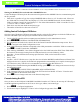


Table Of Contents
- Control Techniques Variable-Speed Drive (VSD) Interface
- Overview
- Cautions, Warnings, and Notices
- Compatible Drives and E2 Versions
- Before Beginning Setup
- 1. Fitting the correct RFI filter(s) at the power input to the drive,
- 2. Mounting the drive against the surface of the RFI filter correctly, removing all paint or non-conducting coatings so that the drive and the RFI filter make good direct electrical contact,
- 3. Ensuring the filter is connected to the drive using only the wires provided (with no extensions),
- 4. Using a shielded (screened) or steel wire armored cable to connect the drive to the motor, with the shield connected to the drive gland plate by a good high-frequency connection (using either the conductive cable glands or the SE11 optional cable ...
- 5. Grounding the shield of the motor cable to the ground terminal of the motor frame using a link that is as short as possible and not exceeding 50 mm (2 in) in length (a full 360° termination of the shield to the motor terminal housing, if metal, i...
- 6. Ensuring the cables carrying the AC supply and the ground to the filter are at least 100 mm (4 in) from the drive and motor cable,
- 7. Avoiding locating noise-sensitive circuits in a zone extending 0.3m (12 inches) all around the drive, and
- 8. Ensuring the motor cables do NOT run in parallel with control signal cables.
- VSD Input Wiring
- MODBUS Networking
- Figure 2 - MODBUS Daisy Chain for CT VSD Drives
- Connection to E2
- Connection to VSDs and the CT Drive Interface
- CPC requires that all MODBUS network connections to Control Techniques VSDs use a CT Drive Interface (P/N 535-2725). This assembly, which plugs into the RJ45 MODBUS jack on the VSD, provides the noise filtering circuitry recommended by Control Techni...
- 1. Using the shielded Ethernet cable included in the CT Drive Interface Kit, connect the CT Drive Interface box to the RJ45 jack on the VSD. Do not use any other Ethernet cable except the cable supplied in the CT Drive Interface kit.
- 2. Connect the MODBUS network cable to the RS485 network connector on the CT Drive Interface. Wire all 485+ terminals on the E2 and CT Drive Interfaces to the same wire color, and wire all 485- terminals to the other wire color. All bare shield wires...
- 3. Terminate the two devices at the endpoints of the MODBUS daisy chain. For the E2, the termination jumpers will be next to the COM port connector. For the VSDs, use the termination jumpers on the CT Drive Interface. Set the jumpers of the end devic...
- CPC requires that all MODBUS network connections to Control Techniques VSDs use a CT Drive Interface (P/N 535-2725). This assembly, which plugs into the RJ45 MODBUS jack on the VSD, provides the noise filtering circuitry recommended by Control Techni...
- Manually Configuring the VSDs to Enable MODBUS Communication
- Commander SE:
- Commander SK:
- For the Commander SK, follow the steps below in order:
- 1. Inhibit or disable the drive.
- 2. Set access to Level 3 (set parameter 10 to “L3”).
- 3. Reset the drive to USA defaults (set parameter 29 to “USA”).
- 4. Set the Drive Config (parameter 5) to “Pr.”.
- 5. Set access to Level 3 (set parameter 10 to “L3”).
- 6. Set the SERIAL COMMS BAUD RATE (parameter 43) to “19.2” (19200 baud).
- 7. Set the SERIAL COMMS ADDRESS (parameter 44) to a unique MODBUS address number from 1 to 127.
- 8. Do not set any other parameters. Exit to save changes.
- For the Commander SK, follow the steps below in order:
- Unidrive SP:
- Sharing the MODBUS Network with Other MODBUS Devices
- Adding Control Techniques VSD Drives
- Once the Control Techniques VSDs are networked properly, assign the E2 COM port to which the VSDs are connected as a MODBUS port, and specify the number of drives on the network.
- 1. Log in to the E2 controller with a username/password that has Level 4 (Administrator) access.
- 2. Press (731 (GENERAL CONTROLLER INFORMATION).
- 3. Port assignments are made in the “Serial” tab of the General Controller Information setup screens. Press c+3 to navigate to the Serial Configuration screen.
- 4. In the COM Connection field that corresponds to the COM port number to which the VSDs are connected, press $ - LOOK UP and select “MODBUS.”
- 5. After selecting “MODBUS,” four fields will appear below the COM Connection field. These fields define the format of the messages coming from the VSDs and must be set to the following values:
- 6. When you have finished entering the MODBUS settings, press ) to save changes and return to the System Information menu.
- 7. Press (772 (CONNECTED I/O BOARDS AND CONTROLLERS).
- 8. In the Connected I/O screen, locate the field in the ECT Devices box labeled “CT Drive.” Enter the total number of VSDs on the network in this field.
- 9. Press ) to save changes and return to the Network Setup menu.
- Once the Control Techniques VSDs are networked properly, assign the E2 COM port to which the VSDs are connected as a MODBUS port, and specify the number of drives on the network.
- Commissioning the VSD
- Once you have set the COM port for MODBUS and added a number of CT drives, the next step in VSD setup is to edit the application parameters in the E2 to set drive type, address, and control type:
- 1. Press (5 - Configured Applications
- 2. Use the arrow keys to highlight “CT Drive” in the Configured Apps menu. Press e.
- 3. If multiple CT drives are set up, highlight the name of the drive you wish to set up and press e.
- 4. The CT Drive Status screen should be visible. From this screen, press % to access the CT Drive setup screens. The first setup screen shown will be “General.”
- Screen 1: General
- Figure 5 - CT Screen 1: General
- 5. Enter a name for the VSD in the “Name” field.
- 6. Enter the MODBUS address for this drive in the “Physical Addr” field.
- 7. Choose the VSD model type (Commander SK, Commander SE, or Unidrive SP) in the Drive Type field.
- 8. In the Control Method field, select “0-10V Reference” if controlling drive speed from an analog point, or “MODBUS Network” if the E2 will control drive speed directly through the MODBUS interface.
- 9. Press ) to save these changes and exit.
- 10. Remain on the CT Drive Status screen. You should see live values appearing in the “Current Conditions” status fields (such as Hz/RPM) as the E2 makes connections between the CT Drive application inputs and outputs and the VSD’s inputs and o...
- 11. When the Setpt Status field shows “In Sync” or “Sync/Error,” press % to return to the CT Drive setup screens. Complete the drive programming by setting the necessary setpoints in the Setpoints, Alarms, and Advanced tabs.
- Once you have set the COM port for MODBUS and added a number of CT drives, the next step in VSD setup is to edit the application parameters in the E2 to set drive type, address, and control type:
- VSD Association With E2 Control Applications
- To associate an application with a CT VSD, navigate to the application’s setup screens, locate the field that determines device type or fan type, and set that field to “CT Drive.”
- Condenser & AHU
- 1. Press (5 - Configured Applications.
- 2. Highlight either “Condenser” or “AHU” in the Configured Apps menu, and press e.
- 3. If more than one application, highlight the name of the application you wish to set up in the Summary Screen and press e.
- 4. From the status screen, press % to access the application setup screens.
- 5. Locate the “Fan Type” field on screen C1: General. Highlight this field, press $, and select “CT Drive” as the fan type.
- 6. Navigate to the screen where the advanced VS setup parameters are (screen C4: VS Setup for Condensers, screen C8: Adv Fan for AHU).
- 7. Locate the field named “CT Drive.” Highlight this field, press $, and select the name of the CT Drive application you wish to assign to this application.
- 8. Press ) to save changes and exit.
- Suction Group & Enhanced Suction Group
- 1. Press (5 - Configured Applications.
- 2. Highlight either “Suction Group” or “Enhanced Suction Group” in the Configured Apps menu, and press e.
- 3. If more than one application, highlight the name of the application you wish to set up in the Summary Screen and press e.
- 4. From the status screen, press % to access the application setup screens.
- 5. In Screen 1: General, if you have not set up the total number of compressor stages in the rack, enter the correct number in the “Num of Stages” field. This will cause the “C6: Comp Setup” tab to be visible.
- 6. Press c+6 to navigate to the Comp Outs screen.
- 7. For stage #1 in the Comp Outs screen, highlight the “TYPE” field and set this field to “CTdr” (CT Drive). This assigns stage 1 of the rack to be a VS compressor driven by a CT VSD.
- 8. Press c+8 to navigate to the VS screen.
- 9. Locate the field named “CT Drive.” Highlight this field, press $, and select the name of the CT Drive application you wish to assign to this application.
- 10. Press ) to save changes and exit.
- Configuration and Synchronizing Configuration Between the E2 and Control Techniques VSDs

technical bulletin
Document Part # 026-4122 Rev 1 16-JUN-2008 Page 1 of 10
©2008 Emerson Climate Technologies Retail Solutions, Inc. This document may be photocopied for personal use.
Visit our website at http://www.emersonretailsolutions.com/ for the latest technical documentation and updates.
CO
MP
U
TER PR
OC
E
SS
CO
NTR
O
L
S
®
Control Techniques Variable-Speed Drive
(VSD) Interface
Overview
The E2 RX, BX, and CX series of controllers features integration with several models of variable-speed drives
(VSDs) manufactured by Control Techniques, a division of Emerson Industrial Automation. The E2 communi-
cates with the VSD via an RS485 MODBUS network, which allows easier wiring setup and more detailed status
and fault information to be communicated to the E2 than traditional VSDs driven with I/O points.
All E2 control applications that can use VSDs — such as variable-speed condenser fans, AHU fans, and VS
compressors — support selection of Control Techniques drives, making software setup quicker and easier.
Cautions, Warnings, and Notices
Compatible Drives and E2 Versions
The E2 controller’s RS485 MODBUS interface communicates with the following Controller Techniques VSD
models:
• Commander SK - Requires E2 version 2.64F01 or above
• Commander SE - Requires E2 version 2.40F01 or above
• Unidrive SP - Requires E2 version 2.40F01 or above
Before Beginning Setup
The networking and configuration instructions in this technical bulletin assume the Control Techniques VSDs are
properly installed, tuned, and programmed by the installer. It is critical that the proper filters, wiring, shielding,
and grounding are done to minimize the EMI generated by these drives. The following is a list of items that must
be addressed to insure proper system operation. Refer to the drive manual on how to do the following:
1. Fitting the correct RFI filter(s) at the power input to the drive,
WARNING! If an E2 has Commander SK variable speed drives
configured, do NOT remotely upgrade this unit to 2.64F01 and
above if the current version is earlier than 2.64F01. The E2 will
lose communication with Commander SK drives when upgraded.
A technician must be on-site to clean out the Commander SK and
reprogram (follow the instructions in this document to program).
WARNING! Inhibit or disable the VSD before making program-
ming changes. Refer to the VSD’s manufacturer’s instructions
for information on inhibiting the drive.