
User`s guide


BYPASSING & ISOLATING
(continued)
InstallationManual ASCOG,Q,S,U7ATB,7ACTB,7ADTB
p a g e 3 --- 4
ASCO Power Technologies 381333–415 A
RETURN TO SERVICE
This procedure explains how to return the automatic
transfer switch (ATS) to service after inspection and
maintenance. Observe the Bypass Switch Position
indicator and lights). Refer to Figures 3–7 through 3–10.
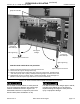
1. Slide the transfer switch (ATS) into the enclosure
(isolation contacts facing inward) until its crank pins
engage the latch plates on both sides. Substantial force
is requir e d to overcome deten ts on the rails. Next push
in side rail carriage. On 4000 A first retract the two
legs and lock them in place. See Figures 3–7a and
3–7b. Then close enclosure door(s).
Close the enclosure door to prevent personal
injury in case of electrical system fault.
NOTICE
Align the position indicator. Do not leave
thehandleinanintermediateposition.
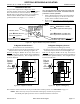
unfold
crank
position
window
clockwise – draw s in the Transfer Switch
CONN
TEST
ISOLATE
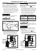
Figure 3–8. Isolation Handle.
2. Turn the Isolation Handle clockw ise (approx. 7 turns,
approx. 8 turns for 4000 A) until the window shows
TEST. The ATS can be tested now without load
interruption (see page 2–1).
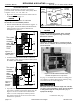
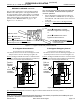
E
L
N
Turn crank
clockwise
until
window
shows
TEST.
ATS
Bypass Switch
Figure 3–9. ISOLATE to TEST position.
NOTICE
Solenoid interlock prevents closing the isolation
contacts until the A TS is in the same
position as
the Bypass Switch.
3. Observe which Bypass Switch Position indicator is
black (NORMAL or EMERGENCY)atBypassSwitch
Handle. This shows the source connected to the load.
4. Observe which Transfer Switch Connected To light is
on (Normal or Emergency) on the door. This is the
position of the Transfer Switch. If it is not in the
same position as the Bypass Handle change the
position of the Transfer Switch as follows:
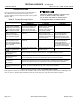
To change the position of transfer switch
Operate to NORMAL OperatetoEMERGENCY
Turn Tra nsf er Control
switch to Retransfer
Delay Bypass.
Turn Tra nsf er Control
switch to Transfer Test
(hold 15 seconds).*
Connected To Normal
light should come on.
Connected To Emergency
light should comes on.
* If Feature 2B time delay i s used, there will be a delay
before transfer to Emergency.
NOTICE
With Normal available, the ATS will not stay in the
emergency position unless Feature 3A time delay
is used (at least 30 seconds).
Do not close the isolation contacts unless the
Transfer Switch (ATS) and Bypass Switch are in
thesameposition!
5. When the t ransfer switch is in the same position as
the Bypass Switch handle, continue turning the
Isolation Handle clockwise (approx. 16 turns, approx.
12 turns for 4000 A) until the window shows CONN
(connected).
E
L
N
Turn crank
clockwise
until window
shows
CONN
(connected).
ATS
Bypass Switch
Figure 3–10. TEST to CONNECTED position.
Continued on next page