
User`s guide


INDEX
Installation Manual
ASCO G, Q, S, U 7ATB, 7ACTB, 7ADTB
Printed in U.S.A.
Copyright ASCO Power Technologies, L.P. 2014
381333–415 A
A
Alarm Reset pushbutton, 1–4, 2–2
ASIisASCOServicesInc.
customercare@asco.com
800–800–2726(ASCO)
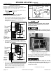
auxiliary circuits, 1–2
B
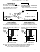
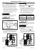
bus connections, 1–2
bypassing the ATS, 3–1
C
catalog number, i
cleaning, 2–1
closed–transition transfer, 1–4
connections
line, 1–2
controller
see Controller User’s Guide
381333–126
D
delayed–transition transfer, 1–4
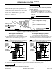
drawout, transfer switch, 3–2, 3–3
E
electrical opera tion, 1–3, 1–4
Emergency Source Accepted light,
1–3, 1–4
Engine Control selector switch
Auto position, 2–1
engine starting contacts, 1–2
Extended Parallel Time light, 1–4, 2–2
F
Failure to Synchronize light, 1–4, 2–2
foundation, 1–1
frequency, generator, 2–2
functional test , 1–3, 1–4
H
harness, 1–2
HELP
customercare@asco.com
800–800–2726(ASCO)
I
inspection, 3–1
installation, 1–1 through 1–4
isolating the ATS, 3–2
L
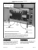
lights, 1–3, 1–4
Load Disconnect Active light, 1–4, 2–2
lubrication, 2–1
M
maintenance, preventive, 2–1
maintenance handle, 2–2
warning, 2–2
manual load transfer, 2–1
warning, 2–2
N
nameplate, cover
Normal Source Accepted light, 1–3
O
operation
electrical, 1–4
manual, 2–2
warning, 2–2
P
parts, 2–1
phase rotation check, 1–3
preventive maintenance, 2–1
problem, 2–2
R
rating label, cover
removal of shipping angles, 1–1
removal of shipping skid, 1–1
replacement parts, 2–1
return to service, 3–4
S
service
ASCOServices,Inc.(ASI),2–1
customercare@asco.com
800–800–2726(ASCO)
settings
see Controller User’s Guide
381333–126
shipping angles, 1–1
warning, 1–1
shipping skid, 1–1
support legs, 3–3
T
test, functional, 1–3, 1–4
testing power cables, 1–2
time delays, 2–1
see Controller User’s Guide
TS Locked Out light, 1–4, 2–2
Transfer Control selector switch
Retransfer Delay Bypass, 1–4
Transfer Test, 1–4
Transfer Switch Connected To Emer-
gency light, 1–4
Transfer Switch Connected To
Normal light, 1–4
transfer test, 1–4, 2–1
transfer to emergency, 1–4, 2–1
transfer to normal, 1–4, 2–1
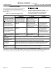
troubleshooting, 2–2
V
voltage checks, 1–3
voltage, pickup and dropout settings
see Controller User’s Guide