
User`s guide

INSTALLATION
(continued)
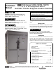
Installation Manual ASCO G, Q, S, U 7ATB, 7ACTB, 7ADTB
page 1---2 ASCO Power Technologies 381333–415 A
De–energize the conductors before making any
line or auxiliary circuitry connections. Be sure that
Normal and Emergency line connections are in
proper phase rotation. Place engine generator
starting control in the OFF position. Make sure
engine generator is not in operation.
Testing Power Conductors
Do not connect the power conductors to the ATB until
they are tested. Installing power cables in conduit, cable
troughs, and ceiling-suspended hangers often requires
considerable force. The pulling of cables can damage
insulation and stretch or break the conductor’s strands.
For this reason, after the cables are pulled int o position,
and before they are connected they should be tested to
verify that they are not defective or have been damaged
during installation.
NOTICE
Protect the switch from construction grit and metal
chips to prevent malfunction or shortened life of
the ATB switch.
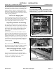
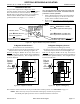
Connecting Power Conductors
A Wiring Diagram is furnished with the ATB. All wiring
must be made in accordance with the local codes. After
the power cables have been tested, connect them to the
appropria te terminal lugs on the Bypass Switch as shown
on the wiring diagram provided with this ATB. Make
sure that the lugs provided are suitable for use with the
cables being installed. Standard terminal lugs are
solderless screw type and will accept the wire sizes listed
on the drawings provided with the ATB. Be careful when
stripping insulation from conductors; avoid nicking or
ringing the conductor. Remove surface oxides from
conductors by cleaning with a wire brush. Follow
conductor manufacturer’s instructions when aluminum
conductor is used. Apply joi nt compound to conductor,
then carefully wipe away excess compound. Tighten the
cable lugs to the torque specified on the rating label.
NOTICE
Be sure that the Normal and Emergency power
connections are in proper phase rotation.
Bus Connections
If bus connection is used, use SAE grade 5 hardware to
connect bus to appropriate terminal plates on bypass
switching device. Wipe off bus surfaces before they are
joined. If bus is dirty, gently clean surfaces with a
non-flammable solvent. Avoid touching cleaned surfaces.
Do not breathe cleaning solvent vapors.
UseSAEgrade5hardwareandtightentheboltedjointsto
thetorquespecifiedinTableA.
NOTICE
The reliability of the connection depends
on how clean and how tight the joint is.
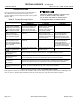
Table A. Tightening torque values for bolted joints.
Bolt Diameter
(Grade 5 hardware)
in inches
Recommended
Tightening Torque
in foot pounds
5/16 12
3/8 20
1/2 50
5/8 95
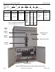
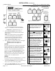
Harnesses
All internal connections are made at the factory . The
bypass switch, transfer switch, and control panel are
joined together by an interconnecting wire harness. The
disconnect plugs are already engaged on enclosed
switches. For open–type switches, the plugs must be
engaged after installation is completed. Align harness
plugs with sockets in the control and push them together
until they are secure.
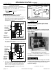
Controller Ground
A grounding wire must be connected to the controller’s
lower left mounting stud. Because the controller is
mounted on the enclosure door, a conductive strap must
be used between the enclosure and the door. This
connection provides proper grounding which does not
rely upon the door hinges.
Engine Starting Contacts
and Auxiliary Circuits
The engine control conta ct si gnal connections and
auxiliary circuits are located on terminal block TB as
shownontheWiring Diagram provided with the ATB.
Connect the signal wires to the appropriate terminals.