
User`s guide

INSTALLATION (continued)
Installation ManualASCO G, Q, S, U 7ATB, 7ACTB, 7ADTB
p a g e 1 --- 3381333–415 A ASCO Power Technologies
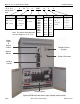
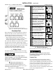
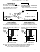
observe
these
lights
Figure 1-3. Standard controls and indicators.
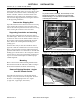
Functional Test
Read all instructions on the Wiring Diagrams and labels
affixed to the ATB. Note the control features that are
provided and review their operation before proceeding.
After installing the ATB check the following:
– Bypass Handle should be in the OPEN position.
– Isolation Handle should be in the CLOSED position.
– Transfer switch should be in NORMAL position.
(For ACTB and ADTB the CN transfer switch should be
CLOSED and the CE transfer switch should be OPEN).
If handles are not in correct positions, follow instructions
for Bypassing and Isolating the automatic transfer switch
in Section 3. Do not force the handles. Electrical
interlocks prevent a wrong sequence of operation.
1–VoltageChecks
First check nameplate on transfer switch; ra ted voltage
mustbethesameasnormalandemergencylinevoltages.
Use extreme caution when using a meter to
measure voltages. Do not touch power terminals;
shock, burns, or death could result!
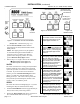
Perform steps 1–6 at the right. Observe the status lights.
See Figure 1–3.
Black square means light is on.
White square means light is off.
* If necessary, adjust voltage regulator on generator per the
manufacturer’s recommendations. The ATB will respond only to
rated voltage specified on the nameplate.
Now continue to 2 – Electri cal Operation.
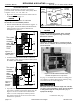
1
Close the normal source circuit
breaker. The Transfer Switch
Connected To Normal and the
Normal Source Accepted lights
should come on.
2
Use an accurate voltmeter to
check phase to phase and
phase to neutral voltages pres -
entatthetransferswitchnormal
source terminals.
3
Close the emergency source
circuit breaker. Turn the Engine
Control switch to Run to start
the generator. The Transfer
Switch Connected To Normal &
Emergency Source Accepted
lights should come on.
4
Use an accurate voltmeter to
check phase to phase and
phase to neutral voltages pres -
ent a t t he transfer switch emer-
gency source terminals.*
5
Useaphaserotationmeterto
check phase rotation of emer-
gency source; it must be the
same
as the normal source.
A
B
C
6
Turn Engine Control switch to
Auto to stop the generator. The
Emergency Source Accepted
light should go off. Then put the
starting control selector switch
(on generator set) in automatic
position. Close enclosure door.
2 – Electrical Operation
This procedure checks electrical operation of the ATS.
Be sure to close the enclosure doors before
proceeding to prevent person injury in case of
electrical system fault.
Transfer Test
The ATS should be bypassed and isolated. Follow
instructions for Bypassing and Isolating the automatic
transfer switch in Section 3. Both normal a nd emergency
sources must be available and the emergency source
generator (if used) must be capable of being started; put
engine starting control in automatic position. The
Transfer Switch Conne cted to Normal light and the Normal
Source Accepted light should be on.