
User`s guide

INSTALLATION
(continued)
Installation Manual ASCO G, Q, S, U 7ATB, 7ACTB, 7ADTB
page 1---4 ASCO Power Technologies 381333–415 A
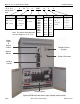
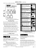
operate
this switch
observe
these
lights
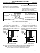
Figure 1-4. Standard controls and indicators.
(Transfer Test continued from page 1–3)
1. Turn the Isolation Handle counterclockwise
(approximately 12 turns) until the window shows
TEST position.
NOTE: Theenginegeneratormaybesignalled
to start while turning the Isolation Handle. If
emergency source is available, the ATS may
operate to the emergency position. If it does,
operate Retransfer Delay Bypass switch.
2. Perform steps 1–5 at right. Observe the status lights.
Black square means light is on.
White square means light is off.
7ACTB
The load is transferred via overlap (closed) transition.
Transfer switch CE closes, then transfer switch CN
opens. The operat ion is reversed for retransfer back
to normal. If you do not want closed–transition
transfer, press the Closed Transition Bypass button
(Figure 1–5) while the controller display shows
Waiting for In–Sync. Thisactioncausesopen–transi-
tion (momentary load interruption) transfer to the
opposite source, if conditions permit.
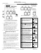
7ADTB
The load is disconnected and light (Figure 1–6) comes
on during the delayed–transition transfer delay.
3. Turn the Isolation Handle clockwise (approximately 12
turns) to the CONN (connected) position.
4. Push in the Bypass Handle and turn it counterclock-
wise until the OPEN indicator shows green.
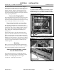
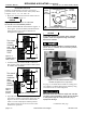
7ADTB light is
on when load is
disconnec ted
7ACTB alarm lights
(see troubleshooting)
7ACTB buttons
Figure 1-5. 7ACTB controls. Figure 1-6.
7ADTB controls
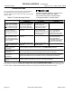
1
The Transfer Switch Connected to
Normal and Normal Source Ac-
cepted lights should be on.
Load
Disconnect
Active
2
Turn and hold Transfer Control
switch clockwise to Transfer T est
until the engine starts and runs
(within 15 s ec.). The Emergency
Source Accepted light should
come on.
Load
Disconnect
Active
3
Transfer switch will operate to the
Emergency position after Feature
2B time delay. The Transfer
Switch Connected to Emergency
light should come on and the
Transfer Switch Connected to
Normal light should go off
(7ACTB you might see and hear
the brief overlap transfer).
Load
Disconnect
Active
4
Transfer switch will operate back
to Normal position after Feature
3A time delay. For immediate
retransfer turn Transfer Co ntrol
counterclockwise to Retransfer
Delay Bypass.TheTransfer
Switch Connected To Normal light
should come on; Transfer Switch
Connected to Emergency light
should go off.
Load
Disconnect
Active
5
The engine–generator will stop
after the Feature 2E time delay
(unloaded running engine cool-
down). The Emergency Source
Accepted light should go off.
Load
Disconnect
Active
This completes the Functional Test of the ATB.