
User`s guide

SECTION 2 TESTING & SERVICE
Installation ManualASCO G, Q, S, U 7ATB, 7ACTB, 7ADTB
page 2---1381333–415 A ASCO Power Technologies
TRANSFER TEST
Test the Automatic Transfer Switch portion of the 7000
Series ATB at least once a month. This procedure checks
the electrical operation of the Transfer Switch and
Controller. Turn the Engine Control switch to Auto and
put the engine–generator starting control (at the
engine–generator set) i n automatic mode.
In the test the gener ator wil l start, the load will be
transfer red to the Em erg en c y sourc e, then back to the
Normal source. An interruption to the load will occur,
unl ess the Transfer Switch contac ts are bypassed before the
test. See pages 3–1 and 3–2 for bypassing and isolating
inst r u ction s if no inter r u p tio n of lo ad is requ ir e d.
Be sure to close the enclosure doors before
proceeding to prevent person injury in case of
electrical system fault.
Perform the Electrical Operation – Transfer Test proce-
dure on pages 1–3 and 1–4.
PREVENTIVE MAINTENANCE
Reasonab le car e in prev en tiv e main ten an ce wil l insur e hig h
reliability and long life for the 7000 Series ATB. An annual
preventive maintenance program is recommended.
ASCO Services, Inc. (ASI) is ASCO Power
Technologies’ national service organization. ASI
can be contacted at 1–800–800–2726 for informa-
tion on preventive maintenance a greements.
Checklist f or Yearly Inspection
Hazardous voltage capable of causing shock,
burns, or death is used in this switch.
Deenergize both Normal – Emergency power
sources before performing inspections!
Clean the ATS enclosure. Brush and vacuum away
any excessive dust accumulation. Remove any
moisture with a clean cloth.
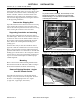
Check the transfer switch contacts
.Remove
transfer switch barriers and check the condition of
the contacts. Replace contacts when pitted or worn
excessively. Reinstall the barriers carefully.
Maintain transfer switch lubrication.Ifswitchis
sub jec ted to severe dust or abnorm al operating
conditions, renew factory lubrication on all
movements and linkages. R elubricate solenoid
oper ato r if TS coil is replac e d. Don ’t use oil; order
lubrication kit 75-100.
Check all cable connections & retighten them.
REPLACEMENT PARTS
Replacement parts are available in kit form. When
ordering parts provide the Serial No., Bill o f Mate rial
No. (BOM), a nd Catalog No. from the transfer switch
nameplate. For service call ASCO Services at
1–800–800–2726; you will be put in contact with your
local ASI office.
MANUAL LO AD TRANSFER
This procedure manually transfers load to other source i f
the Transfer Switch or Control Panel are out of service.
Close enclosure doors to prevent personal
injury in case of electrical system fault.
1. Be sure that the Bypass Handle i s CLOSED on
either Emergency or Normal (see page 3–1).
2. Be sure that the Isolation Handle is in the TEST or
ISOLA TE position (see page 3–2).
3. TurntheBypassHandlecounterclockwisetoOPEN
the Bypass Switch. Then Bypass to the other source
(see page 3–1).
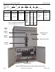
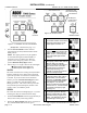
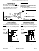
MAINTENANCE HANDLE
Bypass and isolate the Transfer Switch before
using the maintenance handle! See pages 3–1
and 3–2. Remove the hub and handle after using
them and store on frame.
Turn counterclockwise
to Emergency.
Turn clockwise
to Normal.
insert
handle
into hole
Grasp
handle
firmly
slide hub
onto shaft
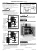
for 7ACTB & 7ADTB
slide hub onto
shaft & insert
pin
Pull out
shaft to operate
Emergency contacts.
Push in
shaft to operate
Normal contacts.
for 7ATB
Turn counterclockwise
to OPEN contacts.
Turn clockwise to
CLOSE contacts.
Figure 2-1. Maintenance handle and hub.