
User`s guide

TESTING & SERVICE
(continued)
InstallationManual ASCOG,Q,S,U7ATB,7ACTB,7ADTB
p a g e 2 --- 2 381333–415 AASCO Power Technologies
TROUBLESHOOTING
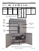
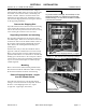
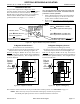
Note any optional accessories that may be furnished on
the ATB and review their operation. Refer to any
separate drawings and/or instructions that may be packed
with the ATB.
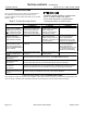
Table B. Trouble-Shooting Checks.
Hazardous voltage capable of causing shock,
burns, or death is used in this switch.
Do not touch the power or load terminals
of the bypass switch or transfer switch!
PROBLEM
CHECK IN NUMERICAL SEQUENCE
1OPERATION 2 GEN-SET 3VOLTAGE
Engine–generator set does
not start when the Transfer
Control switch is turned and
held
in Transfer Test position
or when normal source fails.
Hold Transfer Test switch 15
seconds or the outage must
be long enough to allow for
Feature1Ctimedelayplus
engine cranking and star ting.
Starting control must be in the
automatic position. Batteries
must be charged and
connec ted. Check wiring to
engine starting contacts.
–
Transfer switch does not
transfer the load to the
emergency source after the
engine–generator set starts.
W ait for Feature 2B time delay
to time out.
Generator output circuit
breaker must be closed.
Generator frequency must be
at least 95% of nominal (57 Hz
for a 60 Hz system.) *
Voltmeter sho uld read at least
90% of nominal phase to
phase voltage between
terminals EA and EC (or EL1
and EL2 for 2 po le switches)*
Transfer switch does not
transfer the load to normal
source when normal returns
or when the Transfer Control
switch is released.
W ait for Feature 3A time delay
to time out.
–
Voltmeter sho uld read at least
90% of nominal phase to
phase voltage between
terminals NB and NC, NC and
NA , and NA and NB (or NL1
and NL2 for 2 po le switches).
Gen. does not stop after load
retransfer to normal source.
W ait for Feature 2E time delay
to time out.
Starting control must be in the
automatic position.
–
7ACTB
Failure to Synchronize
light comes on.
Conditions of Normal or Emergency Sources not suitable for closed transition transfer.
Recheck voltage and frequency of both sources. Press Alarm Reset pushbutton.
7ACTB
Extended Parallel Time
light comes on.
CN and CE contacts are closed longer than setting in the controller. Open the disconnected
source circuit breaker, then call your nearest ASCO Service Center for assistance.
7ACTB
TS Locked Out
light comes on.
Transfer lockout operation has occured; transfer switch is disabled from automatic operation.
Open the disconnected source circuit breaker, then call your nearest ASI for assistance.
7ADTB
Load Disconnect Active light
comes on.
Delayed transition transfer operation. If load is disconnected longer than the sett ing in Group 5
controller (see User’s Guide 381333–126), then contact ASI for assistance.
* These are factory settings. Refer to Controller User’s Guide.
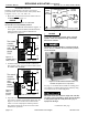
If the prob l em is isolated to circu its on the contr ol l er or the transfer switc h, cal l your loc al AS CO Power Techn ol og ies sales
office or A SI at 1–800–800–2726. F urnish the Serial No. and Catalog No. from the transfer switch nameplate.