4664RevBBQIG.fm Page 1 Friday, January 11, 2013 6:13 PM Quick Installation Guide 00825-0100-4664, Rev BB January 2013 Rosemount 8712 / 8700 Series Rosemount 8712E Magnetic Flowmeter System (Transmitter and Sensor) Start Step 1: Pre-Installation Step 2: Handling Step 3: Mounting Step 4: Installation (Flanged Sensors) (Wafer Sensors) (Sanitary Sensors) Step 5: Grounding Step 6: Wiring Step 7: Basic Configuration Product Certifications End www.rosemount.
4664RevBBQIG.fm Page 2 Friday, January 11, 2013 6:13 PM Quick Installation Guide 00825-0100-4664, Rev BB January 2013 Rosemount 8712 / 8700 Series © 2013 Rosemount Inc. All rights reserved. All marks property of owner. Emerson Process Management Emerson Process Emerson FZE Management Flow P.O.
4664RevBBQIG.
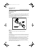
664RevBBQIG.fm Page 4 Friday, January 11, 2013 6:13 PM Quick Installation Guide 00825-0100-4664, Rev BB January 2013 Rosemount 8712 / 8700 Series Figure 1. Rosemount 8712 Dimensional Drawing WITH STANDARD COVER 9.01 (229) 2.81 (71) 4.31 (109) 3.11 (79) 0.44 (11) 12.02 (305) 11.15 (283) 2.
4664RevBBQIG.fm Page 5 Friday, January 11, 2013 6:13 PM Quick Installation Guide 00825-0100-4664, Rev BB January 2013 Rosemount 8712 / 8700 Series Environmental Considerations To ensure maximum transmitter life, avoid excessive heat and vibration.
4664RevBBQIG.fm Page 6 Friday, January 11, 2013 6:13 PM Quick Installation Guide Rosemount 8712 / 8700 Series 00825-0100-4664, Rev BB January 2013 Electrical Considerations Before making any electrical connections to the Rosemount 8712, consider local and plant electrical standards and be sure to have the proper power supply, conduit, and other accessories necessary to comply with these standards. STEP 2: HANDLING Handle all parts carefully to prevent damage.
4664RevBBQIG.fm Page 7 Friday, January 11, 2013 6:13 PM Quick Installation Guide 00825-0100-4664, Rev BB January 2013 Rosemount 8712 / 8700 Series STEP 3: MOUNTING Upstream/Downstream Piping To ensure specification accuracy over widely varying process conditions, install the sensor a minimum of five straight pipe diameters upstream and two pipe diameters downstream from the electrode plane (see Figure 3). Figure 3.
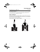
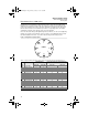
4664RevBBQIG.fm Page 8 Friday, January 11, 2013 6:13 PM Quick Installation Guide 00825-0100-4664, Rev BB January 2013 Rosemount 8712 / 8700 Series Figure 4. Sensor Orientation FLOW FLOW The electrodes in the Rosemount 8705 sensor are properly orientated when the two measurement electrodes are in the 3 and 9 o’clock positions, as shown on the right of Figure 4. The electrodes in the Rosemount 8711 are properly orientated when the top of the sensor is either vertical or horizontal, as shown in Figure 5.
4664RevBBQIG.fm Page 9 Friday, January 11, 2013 6:13 PM Quick Installation Guide 00825-0100-4664, Rev BB January 2013 Rosemount 8712 / 8700 Series STEP 4: INSTALLATION Flanged Sensors Gaskets The sensor requires a gasket at each of its connections to adjacent devices or piping. The gasket material selected must be compatible with the process fluid and operating conditions. Metallic or spiral-wound gaskets can damage the liner. Gaskets are required on each side of a grounding ring.
4664RevBBQIG.fm Page 10 Friday, January 11, 2013 6:13 PM Quick Installation Guide 00825-0100-4664, Rev BB January 2013 Rosemount 8712 / 8700 Series If leakage has not stopped at the suggested torque values, the bolts can be tightened in additional 10% increments until the joint stops leaking, or until the measured torque value reaches the maximum torque value of the bolts.
4664RevBBQIG.fm Page 11 Friday, January 11, 2013 6:13 PM Quick Installation Guide 00825-0100-4664, Rev BB January 2013 Rosemount 8712 / 8700 Series Table 2. Flange Bolt Torque and Bolt Load Specifications for 8705(EN 1092-1) PTFE/ETFE liner PN10 PN 16 PN 25 PN 40 Size (Newton(Newton(Newton(NewtonCode Line Size meter) (Newton) meter) (Newton) meter) (Newton) meter) (Newton) 005 0.5-inch 10 4400 (15 mm) 010 1 inch 20 10100 (25 mm) 015 1.
4664RevBBQIG.fm Page 12 Friday, January 11, 2013 6:13 PM Quick Installation Guide Rosemount 8712 / 8700 Series 00825-0100-4664, Rev BB January 2013 Table 2. (continued) Flange Bolt Torque and Bolt Load Specifications for 8705 (EN 1092-1) Polyurethane, Linatex, Adiprene and Neoprene Liners PN 10 PN 16 PN 25 PN 40 Size (Newton(Newton(Newton(NewtonCode Line Size meter) (Newton) meter) (Newton) meter) (Newton) meter) (Newton) 010 1 inch 20 7040 (25 mm) 015 1.
4664RevBBQIG.fm Page 13 Friday, January 11, 2013 6:13 PM Quick Installation Guide 00825-0100-4664, Rev BB January 2013 Rosemount 8712 / 8700 Series Wafer Sensors Gaskets The sensor requires a gasket at each of its connections to adjacent devices or piping. The gasket material selected must be compatible with the process fluid and operating conditions. Metallic or spiral-wound gaskets can damage the liner. Gaskets are required on each side of a grounding ring. See Figure 8 below. Figure 8.
4664RevBBQIG.fm Page 14 Friday, January 11, 2013 6:13 PM Quick Installation Guide Rosemount 8712 / 8700 Series Table 4. Rosemount Alignment Spacer Table Rosemount Alignment Spacer Table Line Size Dash No. (in) (mm) 0A15 1.5 40 0A20 2 50 0A30 3 80 0B15 1.5 40 AA15 1.5 40 AA20 2 50 AA30 3 80 AA40 4 100 AA60 6 150 AA80 8 200 AB15 1.5 40 AB20 2 50 AB30 3 80 AB40 4 100 AB60 6 150 AB80 8 200 AB15 1.5 40 AB20 2 50 AB30 3 80 AB40 4 100 AB60 6 150 AB80 8 200 DB40 4 100 DB60 6 150 DB80 8 200 DC80 8 100 DD15 1.
4664RevBBQIG.fm Page 15 Friday, January 11, 2013 6:13 PM Quick Installation Guide 00825-0100-4664, Rev BB January 2013 Rosemount 8712 / 8700 Series Flange Bolts Wafer sensors require threaded studs. See Figure 7 for torque sequence. Always check for leaks at the flanges after tightening the flange bolts. All sensors require a second torquing 24 hours after initial flange bolt tightening. Table 5. Rosemount 8711 Torque Specifications Size Code Line Size 15F 0.15 inch (4 mm) 30F 0.30 inch (8 mm) 005 0.
4664RevBBQIG.fm Page 16 Friday, January 11, 2013 6:13 PM Quick Installation Guide Rosemount 8712 / 8700 Series 00825-0100-4664, Rev BB January 2013 STEP 5: GROUNDING Use Table 6 to determine which process grounding option to follow for proper installation. The sensor case should be earth grounded in accordance with national and local electrical codes. Failure to do so may impair the protection provided by the equipment. Table 6.
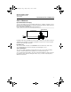
4664RevBBQIG.fm Page 17 Friday, January 11, 2013 6:13 PM Quick Installation Guide 00825-0100-4664, Rev BB January 2013 Rosemount 8712 / 8700 Series Figure 12. Grounding with Grounding Rings or Lining Protectors Grounding Rings or Lining Protectors Figure 13.
4664RevBBQIG.fm Page 18 Friday, January 11, 2013 6:13 PM Quick Installation Guide 00825-0100-4664, Rev BB January 2013 Rosemount 8712 / 8700 Series STEP 6: WIRING Conduit Ports and Connections This wiring section covers the connection between the transmitter and sensor, the 4-20 mA loop, and supplying power to the transmitter. Follow the conduit information, cable requirements, and disconnect requirements in the sections below.
4664RevBBQIG.fm Page 19 Friday, January 11, 2013 6:13 PM Quick Installation Guide 00825-0100-4664, Rev BB January 2013 Rosemount 8712 / 8700 Series Run the appropriate size cable through the conduit connections in your magnetic flowmeter system. Run the power cable from the power source to the transmitter. Run the coil drive and signal cables between the flowmeter sensor and transmitter.
4664RevBBQIG.fm Page 20 Friday, January 11, 2013 6:13 PM Quick Installation Guide 00825-0100-4664, Rev BB January 2013 Rosemount 8712 / 8700 Series STEP 6 CONTINUED... To order cable specify length as quantity desired. 25 feet = Qty (25) 08732-0753-1003 Table 7.
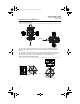
4664RevBBQIG.fm Page 21 Friday, January 11, 2013 6:13 PM Quick Installation Guide 00825-0100-4664, Rev BB January 2013 Rosemount 8712 / 8700 Series STEP 6 CONTINUED... Figure 16. Remote Mount Wiring Diagrams NOTE When using the Rosemount supplied combination cable, the signal wires for terminals 18 and 19 contain an additional shield wire.
4664RevBBQIG.fm Page 22 Friday, January 11, 2013 6:13 PM Quick Installation Guide 00825-0100-4664, Rev BB January 2013 Rosemount 8712 / 8700 Series STEP 6 CONTINUED... Connect the 4–20 mA Analog Signal Cabling considerations If possible, use individually shielded twisted pair cable, either in single pair or multi-pair varieties. Unshielded cables may be used for short distances, provided ambient noise and cross-talk will not adversely impact communication. The minimum conductor size is 0.
4664RevBBQIG.fm Page 23 Friday, January 11, 2013 6:13 PM Quick Installation Guide 00825-0100-4664, Rev BB January 2013 Rosemount 8712 / 8700 Series Powering the Transmitter The 8712E transmitter is designed to be powered by 90-250 Vac, 50–60 Hz or 12–42 Vdc. Before connecting power to the Rosemount 8712E consider the following standards and be sure to have the proper power supply, conduit, and other accessories.
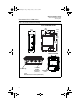
4664RevBBQIG.fm Page 24 Friday, January 11, 2013 6:13 PM Quick Installation Guide Rosemount 8712 / 8700 Series 00825-0100-4664, Rev BB January 2013 8712E Power Supply For AC power applications (90-250 VAC, 50-60 Hz) connect AC Neutral to terminal N and connect AC Line to terminal L1. For DC power applications, connect negative to terminal N (DC -) and positive to terminal L1 (DC +). Ground the transmitter cage via the grounding stud located on the bottom of the transmitter housing.
4664RevBBQIG.fm Page 25 Friday, January 11, 2013 6:13 PM Quick Installation Guide 00825-0100-4664, Rev BB January 2013 Rosemount 8712 / 8700 Series Step 7: Basic Configuration Once the magnetic flowmeter is installed and power has been supplied, the transmitter must be configured through the basic setup. These parameters can be configured through either a local operator interface or a HART communication device. A table of all the parameters are on page 26.
4664RevBBQIG.fm Page 26 Friday, January 11, 2013 6:13 PM Quick Installation Guide Rosemount 8712 / 8700 Series 00825-0100-4664, Rev BB January 2013 Table 11.
4664RevBBQIG.fm Page 27 Friday, January 11, 2013 6:13 PM Quick Installation Guide 00825-0100-4664, Rev BB January 2013 Rosemount 8712 / 8700 Series PRODUCT CERTIFICATIONS Approved Manufacturing Locations Rosemount Inc. — Eden Prairie, Minnesota, USA Fisher-Rosemount Technologias de Flujo, S.A. de C.V.
4664RevBBQIG.
4664RevBBQIG.
4664RevBBQIG.fm Page 30 Friday, January 11, 2013 6:13 PM Quick Installation Guide Rosemount 8712 / 8700 Series 00825-0100-4664, Rev BB January 2013 Table 12. Electrical Data Rosemount 8705 and 8711 Sensors Coil excitation circuit: 40 V DC (pulsed), 0,5 A, 20 W maximum Electrode circuit: in type of explosion protection intrinsic safety EEx ia IIC, Ui = 5 V, li = 0.2 mA, Pi = 1 mW, Um = 250 V Table 13.
4664RevBBQIG.fm Page 31 Friday, January 11, 2013 6:13 PM Quick Installation Guide 00825-0100-4664, Rev BB January 2013 Rosemount 8712 / 8700 Series Figure 21. Declaration of Conformity EC Declaration of Conformity No: RMD 1031 Rev. E We, Rosemount Inc. 12001 Technology Drive Eden Prairie, MN 55344-3695 USA declare under our sole responsibility that the product(s), Model 8712D and Model 8712E Magnetic Flowmeter Transmitters manufactured by, Rosemount Inc.
4664RevBBQIG.fm Page 32 Friday, January 11, 2013 6:13 PM Quick Installation Guide Rosemount 8712 / 8700 Series 00825-0100-4664, Rev BB January 2013 Schedule EC Declaration of Conformity RMD 1031 Rev.