
Data Sheet


Bulletin 71.4:98
3
Temperature Capabilities for Metal Parts
(1)(5)
MATERIAL TEMPERATURE RANGE
Cast Iron
(7)
-40° to 406°F (-40° to 208°C)
WCC Steel -20° to 450°F (-29° to 232°C)
CF8M Stainless steel, Monel
®
, or
Hastelloy
®
C
-40° to 450°F (-40° to 232°C)
Maximum Spring Case Loading Pressure for
Types 98LD and 98HD (Spring Setting Plus
Loading Pressure)
(1)(2)
Type 98LD Spring Case
Cast Iron: 50 psig (3,4 bar)
Steel or Stainless steel: 125 psig (8,6 bar)
Type 98HD Spring Case
Cast Iron: 235 psig (16,2 bar)
Steel or Stainless steel: 300 psig (20,7 bar)
Type 98HHD Spring Case
Cast Iron: 250 psig (17,2 bar)
Steel or Stainless steel: 250 psig (17,2 bar)
Capacities
Types 98L and 98LD: See Tables 3 through 7
Types 98H and 98HD: See Tables 8 through 12
Type 98HH and 98HHD: See Tables 13 through 17
Type 98HM: See Tables 18 through 21
Specications (continued)
• Differential Pressure Capability—Spring-loaded
PTFE packing and tapped connections permit
pressure loading of Types 98LD and 98HD
spring cases.
• Handwheels—Handwheels (standard on the
Types 98LD and 98HD and optional on some
sizes of the Types 98L and 98H) allow easy
pressure setting changes.
• Sour Gas Service Capability—Optional
materials are available for applications handling
sour gases. These constructions comply with
the recommendations of NACE International
Standards MR0175 and MR0103.
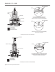
Principle of Operation
Relief or backpressure valves respond to changes in
upstream pressure. Pressure changes register under
the diaphragm (see Figure 2) through a registration
hole in the valve body (through upstream sensing
line connection for Type 98HM). When the pressure
increases beyond the spring setting, the diaphragm
pressure overcomes the spring compression. This
causes the valve plug to move away from the orice.
The ow line through the valve is open and excess
pressure is vented. When upstream pressure drops
back to normal, the valve resumes its closed position.
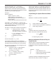
The chart in Figure 3 illustrates the operation of an
NPS 1/2 (DN 15) body used in air service. As the
inlet pressure increases, initial ow occurs at the
bubble point of 10.5 psig (0,72 bar). Flow increases
with further rises in the inlet pressure, reaching
500 SCFH (13,4 Nm
3
/h) at the relief pressure setting
of 12 psig (0,83 bar). Greater capacities are obtained
with higher build-ups over the relief pressure setting,
as shown in the capacity tables.
When the inlet pressure decreases, ow decreases until
the valve reseals to reseat point of 9 psig (0,62 bar).
Shutoff Classication Per ANSI/FCI 70-3-2004
Metal Seats: Class IV
PTFE: Class IV
Elastomer Seats: Class VI
Flow Coefcient
C
1
: 35
Type 98HM Sensing Line Connection
1/2, 1-1/2, or 2 NPT body: 1/8 NPT
3/4 or 1 NPT body: 1/4 NPT
IEC Sizing Coefcients
BODY SIZES,
NPS (DN)
X
T
F
D
F
L
K
m
1/4
0.78 0.50
0.91 0.83
1/2 (15) 0.83 0.69
3/4 and 1
(20 and 25)
0.88 0.77
1-1/2 and 2
(40 and 50)
0.92 0.85
Options
• Handwheel or tee handle for Types 98L, 98H,
and 98HH
• Tapped spring case vent for Types 98L, 98H,
98HH, and 98HM
• Seal washer to permit spring case pressure
loading for Types 98L, 98H, 95HH, and 98HM
1. The pressure/temperature limits in this Bulletin and any applicable standard limitation should not be exceeded.
2. Loading pressure plus spring setting should not exceed maximum inlet pressure.
5. Pressure and/or the body end connection may decrease these maximum temperatures.
7. Not available for Type 98HM.