
Instruction manual

Instruction Manual
D500240X012
A31A Valve
October 2012
11
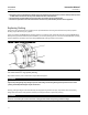
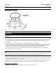
6. Attach the bonding strap assembly (key 131, figure 6) to the shaft with the clamp (key 130, figure 6).
7. Connect the other end of the bonding strap assembly to the valve flange cap screws.
8. For more information, refer to the Packing Maintenance section below.
Installing Single-Flange Valves
WARNING
The edges of a rotating valve disk have a shearing effect that may result in personal injury. To avoid personal injury, keep
clear of the disk edges when rotating the disk.
1. Seefigure5forrecommendedvalveorientation.See table 5 for hex head cap screw specifications.
2. Properly orient the valve according t o the specific application. For optimum performance, install the valve for
reverse flow.
3. Position the v alve between the flanges.Besuretoleaveenoughroomfortheflange gaskets. Install the lower flange
bolts.
4. Select the appropriate gaskets for the application. Flat sheet, spiral wound, or other gasket types, made to the
ASME B16.5 group standard or user's standard, can be used on the valve depending on the service conditions of the
application. Install the gaskets and align the valve and the gaskets.
5. Install the remaining bolts.
6. Tighten the flange bolts in an alternating criss-cross fashion to a torque value of one-fourth of the final bolting
torque. Repeat this procedure several times increasing the torque value each time by a fourth of the final desired
torque. When you get to the final torque value, tighten each flange bolt again to allow for gasket compression.
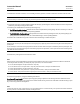
Table 6. Torque Values for Fasteners
FASTENER NOMINAL SIZE
Retaining
Ring
Screws
#10 1/4 5/16 3/8 7/16 1/2 9/16 5/8 3/4 7/8 1 1-1/8
LbfSin LbfSft
41 100 220 400 53 83 119 166 296 480 720 1000
NSm
4.6 11 25 45 72 112 161 225 401 651 976 1356
Gasket
Retaining
Bolts
LbfSin LbfSft
35 81 167 295 39 59 86 119 210 330 480 617
NSm
4.0 9.2 19 33 53 80 117 161 286 447 651 837
Note: These values are based upon standard materials, S66286/N07718 screws and ASTM A193GRB6 bo lts. For other special fastener materials, please contact your Emerson Process Manage
ment sales office.
Maintenance
WARNING
Avoid personal injury from sudden release of process pressure. Before performing any maintenance operations:
D Do not remove the actuator from the valve while the valve is still pressurized.
D Disconnect any operating lines providing air pressure, electric power, or a c ontrol signal to the actuator. Be sure the
actuator cannot suddenly open or close the valve.