
Instruction manual


Instruction Manual
D500240X012
A31A Valve
October 2012
22
3. Using caution to prevent damage to the bearings, insert the required number of journal bearings (key 7) from the
valve body bore into the drive shaft bearing bore. When properly installed, one end of the journal bearing(s) will be
flush with the interior end of the packing box, the other end of the journal bearing(s) will be flush with the valve
body bore.
The drive shaft thrust bearing (key 24) will be installed i n step 5.
4. Insert one journal bearing from the valve body bore into the follower shaft bearing bore so it is flush with the valve
body bore.
5. Insertthedriveshaftintothevalvebodythroughthepackingbox.Pushthedriveshaftthroughthejournalbearing.
Holdthedriveshaftthrustbearing(key24)inthevalvebodyboreagainsttheopeningofthedriveshaftbearing
bore. Push the drive shaft through the bearing bore just enough to hold the thrust bearing.
6. Insert the follower shaft through the bore in the valve body uncovered by removal of the gasket retainer. Hold the
follower shaft thrust bearing (key 24) in the valve body bore against the opening of the follower shaft bearing bore.
Push the follower shaft through t he bearing bore just enough to hold the thrust bearing.
7. Install the valve disk. Place the flat side of the disk on a flat surface. Then, move the valve body from its upright
position and suspend the valve body over the disk so the seal ring/T-slot area is facing up. Align the shaft bores
through the disk with the drive shaft and follower shaft bores. Lower the valve body over the disk using caution not
to dislodge or damage the thrust bearings placed on the ends of the shafts.
8. With the valve disk properly positioned in the valve body, push the drive shaft and follower shaft the rest of the way
through the thrust bearings and into the shaft bores in the valve disk.
9. Align the holes in the shafts with the holes in the disk.
CAUTION
To avoid damage to the taper key, tangential pins, disk pins, valve disk, or shaft(s) resulting from the application of
excessive force, use appropriate care when driving the key or pins into the disk hub and shaft(s). Use the correct tool, and
do not use excessive force.
10. Beforeinstallingthetaperkey,besurethetaperkeydiskshaft joint is free of oil or grease. If necessary, remove any
excess welding material from the taper key.
11. Install the appropriate taper key, tangential pins, and disk pins.
12. Install the taper key by aligning the taper key hole in the shaft with the holes in the shaft boss on the disk. Insert
the taper key. Use a pin punch to drive the taper key until solid contact is felt. Measure the depth of the taper key
head for a reference during the following steps.
a. Drive the taper key in farther as follows:
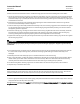
VALVE SIZE, NPS MINIMUM DEPTH TO DRIVE TAPER KEY AFTER INITIAL SOLID CONTACT
NPS 8 CL300, NPS 10 and 12 CL150, & NPS 10 CL300 valves 6 mm (0.219 INCHES)
b. The disk shaft, and taper key assembly must be inspected to verify t hat the taper key spans the entire shaft flat
width. If so, this procedure is complete. If not, the taper key must be driven in farther until this condition is
satisfied. However, do not exceed the following depth limits:
VALVE SIZE, NPS MINIMUM ALLOWABLE DEPTH TO DRIVE TAPER KEY AFTER INITIAL SOLID CONTACT
NPS 8 CL300, and NPS 10 and 12 CL150 10 mm (0.375 INCHES)
NPS 10 CL300 11 mm (0.406 INCHES)
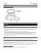
13. After driving the taper key in place, arc spot weld the head of the taper key to the disk as shown in figure 8. For NPS
10 and 12 valves, use an arc spot weld bead of 3/16-inch in diameter. packing box. Install the packing around the
drive shaft.