
Data Sheet
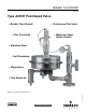


Bulletin 74.3:ACE97
5
Tank Blanketing systems must be properly sized to have
capacity to supply enough blanketing gas to maintain the
setpoint pressure, yet large enough to vent excess gas without
having tank vapor space pressure rise above allowable limits.
Pad valves must not be so large that they cause overpressure.
Sizing must also take into account applicable codes and
standards as they apply to the installation.
For proper sizing of the pad and depad valves, certain
information is required. Proper sizing is essential to protect the
product, the tank, the environment, and personnel.
The following list contains all necessary information to properly size
a valve once system parameters are determined. The customer
must provide the following:
• Pump-in rate (for depad calculation)
• Pump-out rate (for pad calculation)
• Inert (blanketing) gas specic gravity
• Inert gas supply pressure (for pad selection)
• Tank volume (for API sizing both pad and depad)
• Stored uid ash point (for API sizing depad)
• Stored uid boiling point (for API sizing depad)
• Vent gas specic gravity (SG) (for API sizing depad)
• Depad setpoint
• Vent piping backpressure
• Sizing method (Direct Displacement or API 2000)
Direct Displacement
The direct displacement method determines the amount
of blanketing gas required to replace liquid pumped out of the tank
and the amount of gas that must be removed due to liquid pump in.
Direct displacement does not account for uctuating temperature
or other factors that may affect pressure in the vapor space. This
method is typically applied to tanks containing non-ammable,
non-volatile products.
Q
pad
= Q
pump-out
where,
Q
pad
= Required Pad Flow Rate
Q
pump-out
= Required Flow Rate for displacement due to
pump-out (See Table 2)
Q
depad
= Q
where,
Q
depad
= Required Depad Flow Rate
Q
pump-out
= Required Flow Rate for displacement due to
liquid pump-in. (See Table 2)
API 2000
The American Petroleum Institute Standard 2000 (API 2000)
sizing criteria accounts for liquid pump-in and pump-out as well
as contraction and expansion of tank vapors due to heating and
cooling. When using API 2000 methods:
Q
pad
= Q
pump-out
+ Q
thermal
where,
Q
pad
= Required Pad Flow Rate
Q
pump-out
= Required Flow Rate for displacement due to
pump-out (See Table 5)
Q
thermal
= Required Flow Rate due to thermal cooling
(See Table 6)
Q
depad
= Q
+ Q
thermal
where,
Q
pad
= Required Depad Flow Rate
Q
pump-in
= Required Pump-In Rate (See Table 5)
Q
thermal
= Required Flow Rate due to thermal expansion
(See Table 6)
Supplemental Venting
Depending on the method, there can be a signicant difference
in the calculated required capacity. No matter which method is
Pad Valves
In the case of pad valves, the tables are based on 0.97 specic
gravity nitrogen. If it is desired to convert nitrogen ow rates of
another gas, multiply the ow rate value from the capacity table by the
following correction factor in Table 3.
Depad Valves
In the case of depad valves, the tables are based on air (1.0 specic
gravity). Always use the differential pressure between tank pressure
(depad setpoint) and vent header (vapor recovery) pressure to
calculate ow through the depad valve.
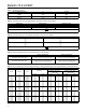
mm mm
0.5 to 3 1 to 7 4 to 10 10 to 25 3.08 78.2 0.105 2.67
0.5 to 7 1 to 17 4 to 6 10 to 15 4.00 102 0.092 2.34
3 to 13 7 to 32 4 to 16 10 to 40 3.73 94.7 0.156 3.96
4 to 10 10 to 25
(1)
16 to 78 40 to 194
(1)
3.73 94.7 0.156 3.96
4 to 10 10 to 25
(1)
16 to 78 40 to 194
(1)
2.90 73.7 0.250 6.35
0.5 to 1.4 psig 0.03 to 0.10 bar 0.25 to 1 psig 0.02 to 0.07 bar
3.80 96.5
0.250 6.35
1.0 to 2.2 psig 0.07 to 0.15 bar 0.25 to 2.0 psig 0.02 to 0.14 bar 0.313 7.95
1. Two nested springs are used.
Table 1. Control Pressure Ranges