Reference Manual 00809-0100-4514, Rev BA January 2008 Rosemount 1154 Alphaline® Nuclear Pressure Transmitter www.rosemountnuclear.
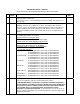
IMPORTANT NOTICE -- ERRATA Model 1154 Product Manual 00809-0100-4514 Rev BA (January 2008) 1 Affected Pages 6-6 2 3-5 No. Description of Change Process Flange –CF3M (Cast version of 316L SST) Drain/Vent Valves –316L SST Process Connections – 3/8-inch Swagelok compression fitting, 316L SST (1/4-18 NPT optional) Change the last paragraph on the page to read as follows: Effect. Date 10/21/09 4/13/12 ”Damping electronics are available as an option.
Reference Manual 00809-0100-4514, Rev BA January 2008 Rosemount 1154 Rosemount 1154 Alphaline® Nuclear Pressure Transmitter NOTICE Read this manual before working with the product. For personal and system safety and optimum product performance make sure you thoroughly understand the contents before installing, using, or maintaining this product. For equipment service needs outside the United States, contact the nearest Rosemount representative.
Reference Manual 00809-0100-4514, Rev BA January 2008 Rosemount 1154 Rosemount Nuclear Instruments, Inc. Warranty and Limitations of Remedy The warranty and limitations of remedy applicable to this Rosemount equipment are as stated on the reverse of the current Rosemount quotation and customer acknowledgment forms. RETURN OF MATERIAL Authorization for return is required from Rosemount Nuclear Instruments, Inc. prior to shipment.
Reference Manual 00809-0100-4514, Rev BA January 2008 Rosemount 1154 Revision Status Changes From June 1999 to January 2008 Page (New) Page (Old) Cover Inside Cover, i, ii, 5-8 & Back Cover 3-5, 6-8 & 6-9 Cover ii, 5-9, 5-10 & Back Cover Throughout i, back cover 3-5, 6-9 & 6-10 2-1,3-1,4-1,5-1, 6-1 2-2 Throughout Cover, i, ii & back cover Cover, i, back page 2-1,3-1,4-1,5-1, 6-1 2-2 2-2 2-4 2-4 2-6 & 2-7 5-7 & 6-9 6-1 6-9 - 2-3 2-4 2-5 2-6 & 2-7 5-8 & 6-10 6-2 6-10 Back Cover - Changes Document
Reference Manual Rosemount 1154 iv 00809-0100-4514, Rev BA January 2008
Reference Manual 00809-0100-4514, Rev BA January 2008 Rosemount 1154 Table of Contents SECTION 1 Introduction Overview . . . . . . . . . . . . . . . . . . . . . . . . . . . . . . . . . . . . . . . . . . . . . . . 1-1 About The Transmitter . . . . . . . . . . . . . . . . . . . . . . . . . . . . . . . . . . . . . 1-1 SECTION 2 Installation Overview . . . . . . . . . . . . . . . . . . . . . . . . . . . . . . . . . . . . . . . . . . . . . . . 2-1 General Considerations . . . . . . . . . . . . . . . . . . .
Reference Manual Rosemount 1154 00809-0100-4514, Rev BA January 2008 SECTION 5 Maintenance and Troubleshooting Overview . . . . . . . . . . . . . . . . . . . . . . . . . . . . . . . . . . . . . . . . . . . . . . . 5-1 Safety Messages . . . . . . . . . . . . . . . . . . . . . . . . . . . . . . . . . . . . . . . . . 5-2 Test Terminals . . . . . . . . . . . . . . . . . . . . . . . . . . . . . . . . . . . . . . . . . . . 5-2 Board Checkout . . . . . . . . . . . . . . . . . . . . . . . . . . . . . . . . . .
Reference Manual 00809-0100-4514, Rev BA January 2008 Rosemount 1154 Physical Specifications . . . . . . . . . . . . . . . . . . . . . . . . . . . . . . . . . . . . 6-6 Materials of Construction. . . . . . . . . . . . . . . . . . . . . . . . . . . . . . 6-6 Electrical Connections. . . . . . . . . . . . . . . . . . . . . . . . . . . . . . . . 6-7 Process Connections . . . . . . . . . . . . . . . . . . . . . . . . . . . . . . . . 6-7 Weight . . . . . . . . . . . . . . . . . . . . . . . . . . . . . . . . . .
Reference Manual Rosemount 1154 TOC-4 00809-0100-4514, Rev BA January 2008
Reference Manual 00809-0100-4514, Rev BA January 2008 Rosemount 1154 Section 1 Introduction OVERVIEW This manual is designed to assist in installing, operating, and maintaining the Rosemount 1154 Pressure Transmitter. The manual is organized into the following sections: Section 2: Installation Provides general, mechanical, and electrical installation considerations to guide you through a safe and effective transmitter installation. Section 3: Calibration Provides transmitter calibration procedures.
Reference Manual Rosemount 1154 1-2 00809-0100-4514, Rev BA January 2008
Reference Manual 00809-0100-4514, Rev BA January 2008 Section 2 Rosemount 1154 Installation Overview . . . . . . . . . . . . . . . . . . . . . . . . . . . . . . . . . . . . . . . page 2-1 General Considerations . . . . . . . . . . . . . . . . . . . . . . . . . . . page 2-1 Mechanical Considerations . . . . . . . . . . . . . . . . . . . . . . . . page 2-2 Electrical Considerations . . . . . . . . . . . . . . . . . . . . . . . . . . page 2-4 Installation Procedures . . . . . . . . . . . . . . . . . . . . .
Reference Manual 00809-0100-4514, Rev BA January 2008 Rosemount 1154 Figure 2-1. Qualified Life vs. Ambient Temperature. Time (Years) Electronics Qualified Life Module Qualified Life Temperature (°F) MECHANICAL CONSIDERATIONS This section contains information you should consider when preparing to mount the transmitter. Read this section carefully before proceeding to the mechanical installation procedure.
Reference Manual 00809-0100-4514, Rev BA January 2008 Rosemount 1154 Transmitters with Flange Options A, D, H, J, L, or M are shipped with Swagelok fittings for process connections. Included are front ferrule, rear ferrule, and nut. Ensure that the fittings are placed on the tubing with the orientation and relative position shown in Detail A, Figure 2-5 on page 2-7. Process tubing used is 3/8-inch outside diameter, and of suitable thickness for the pressure involved.
Reference Manual 00809-0100-4514, Rev BA January 2008 Rosemount 1154 The piping between the process and the transmitter must transfer the pressure measured at the process taps to the transmitter.
Reference Manual 00809-0100-4514, Rev BA January 2008 Rosemount 1154 Signal wiring need not be shielded, but twisted pairs yield the best results. In electrically noisy environments, shielded cable should be used for best results. Do not run signal wiring in conduit or open trays with power wiring, or near heavy electrical equipment. Signal wiring may be ungrounded (floating) or grounded at any place in the signal loop. The transmitter case may be grounded or ungrounded.
Reference Manual 00809-0100-4514, Rev BA January 2008 Rosemount 1154 INSTALLATION PROCEDURES Installation consists of mounting the transmitter and conduit and making electrical connections. Procedures follow for each operation. Mechanical Transmitter Be careful not to break the neck seal between the sensor module and the electronics housing. The threaded interface between the sensor module and the electronics housing is hermetically sealed before shipment.
Reference Manual 00809-0100-4514, Rev BA January 2008 Rosemount 1154 Figure 2-5. Transmitter Dimensional Drawings. ROSEMOUNT 1154DP AND 1154HP 4.7 Max. (119.4) 0.75 (19) Clearance for Cover Removal (typical) 4.72 Max. (119.9) 9 Max. (228.6) Nameplate (remove for zero and span adjust) 1 /2–14 NPT Conduit Transmitter Connection Circuitry (1 Place) (this side) 7 /16–20 UNF (typical) Terminal Connections (this side) 3.7 (94) 1.63 (41.3) Dim. A 3.4 (86.
Reference Manual 00809-0100-4514, Rev BA January 2008 Rosemount 1154 Conduit 1. Seal the conduit threads with thread sealant. (The transmitter conduit seal interface was qualified using Grafoil™ tape.) Conduit threads mate with a standard 1/2–14 NPT male fitting. 2. Starting at zero thread engagement, install the conduit into the transmitter between 4 and 7 turns, or a minimum of 12.5 ft-lb (16.9 N-m).
Reference Manual 00809-0100-4514, Rev BA January 2008 Rosemount 1154 Figure 2-7. Transmitter Terminal Block.
Reference Manual Rosemount 1154 2-10 00809-0100-4514, Rev BA January 2008
Reference Manual 00809-0100-4514, Rev BA January 2008 Section 3 Rosemount 1154 Calibration Overview . . . . . . . . . . . . . . . . . . . . . . . . . . . . . . . . . . . . . . . page 3-1 Calibration . . . . . . . . . . . . . . . . . . . . . . . . . . . . . . . . . . . . . . page 3-1 Calibration Procedures . . . . . . . . . . . . . . . . . . . . . . . . . . . page 3-2 OVERVIEW Each transmitter is factory calibrated to the range specified by the customer.
Reference Manual 00809-0100-4514, Rev BA January 2008 Rosemount 1154 Figure 3-1. Zero Adjustment Range. 20 Output (mA) 600% Zero Elevation 4 –150 –125 –100 –75 –50 –25 0 25 Pressure (inH2O) 600% Zero Elevation➀ 20 Output (mA) 4 0 25 Pressure (inH2O) No Zero Elevation or Suppression➀ 20 Output (mA) 4 0 25 50 75 100 125 150 Pressure (inH2O) 500% Zero Suppression➀ ➀ Graphs based on a Range Code 4 (0–25 to 0–150 inH2O) Rosemount 1154 with a calibrated span of 25 inH2O.
Reference Manual 00809-0100-4514, Rev BA January 2008 Rosemount 1154 Figure 3-2. Zero and Span Adjustment Screws. Zero Span Example (for Range Code 4) Initial transmitter calibration: 25 to 125 inH2O (100 inH2O span with zero suppressed 25 inH2O) Desired transmitter calibration: –75 to –25 inH2O (50 inH2O span with zero elevated 75 inH2O) 1. Adjust the zero to eliminate any existing zero elevation or suppression.
Reference Manual 00809-0100-4514, Rev BA January 2008 Rosemount 1154 Material • Wire: 22-gauge tinned solid copper – Fed Spec QQW343, ASTM B33 • Solder: 60% tin, 40% lead (60/40) – Fed Spec QQ-S-571 • Flux: MIL F 14256, Type A, Fed Spec QQ-S-571 Type RA Method a. Locate the three turret terminals on the component side of the amplifier board. Remove any jumper wires between them (see Figure 3-3). b.
Reference Manual 00809-0100-4514, Rev BA January 2008 Rosemount 1154 1. Apply mid-range pressure and note the error between theoretical and actual output signal. 2. Apply full-scale pressure. Multiply the error noted in step 1 by six and by the rangedown factor: Allowable SpanRangedown Factor = Maximum -------------------------------------------------------------------Calibrated Span 3.
Reference Manual 00809-0100-4514, Rev BA January 2008 Rosemount 1154 The damping adjustment permits damping of rapid pressure variations by adjusting the single-turn trim potentiometer located on the upper right-hand side of the amplifier board (see Figure 3-4). The available settings, when adjusted to the maximum position, provide time-constant values of at least 1.2 seconds for Range Code 4 and 0.8 seconds for Range Codes 5–9 and 0.
Reference Manual 00809-0100-4514, Rev BA January 2008 Rosemount 1154 1. Calibrate the unit per preceding section to output = 4 mA at –100 inH2O and 20 mA at 300 inH2O. 2. Calculate correction factor: 0.75 % ------------------------ × 1, 200 psi = 0.9% differential input 1,000 psi 3. Calculate zero adjustment correction in terms of pressure: 0.9 % × – 100 inH 2 O = – 0.9 inH 2 O 4. Convert pressure correction to percent of input span: – 0.
Reference Manual 00809-0100-4514, Rev BA January 2008 Rosemount 1154 Equalize pressure to both process connections, and turn the zero adjustment until the ideal output at zero differential input is observed. Do not readjust the span potentiometer. If the transmitter does not include zero differential pressure within its calibrated span, the zero effect or zero correction can be determined before the unit is suppressed or elevated to eliminate the zero effect after correcting for the span effect.
Reference Manual 00809-0100-4514, Rev BA January 2008 Section 4 Rosemount 1154 Operation Overview . . . . . . . . . . . . . . . . . . . . . . . . . . . . . . . . . . . . . . . page 4-1 Transmitter Operation . . . . . . . . . . . . . . . . . . . . . . . . . . . . page 4-1 The δ-Cell Sensor . . . . . . . . . . . . . . . . . . . . . . . . . . . . . . . . page 4-3 Demodulator . . . . . . . . . . . . . . . . . . . . . . . . . . . . . . . . . . . . page 4-3 Linearity Adjustment . . . . . . . . . . . . . . . .
Reference Manual 00809-0100-4514, Rev BA January 2008 Rosemount 1154 K1 is a constant. C1 is the capacitance between the high pressure side and the sensing diaphragm. C2 is the capacitance between the low pressure side and the sensing diaphragm. I ref fV p – p = -------------------C1 + C2 Where: Iref is the current source. Vp-p is the peak-to-peak oscillation voltage. f is the oscillation frequency. I diff = fV p – p ( C 2 – C 1 ) Where: Idiff is the difference in current between C1 and C2.
Reference Manual 00809-0100-4514, Rev BA January 2008 Rosemount 1154 Figure 4-2. Electrical Block Diagram. SENSOR DEMODULATOR CURRENT DETECTOR TEST CURRENT LIMITER + OSCILLATOR OSC. CONTROL AMP. + SIGNAL VOLTAGE REGULATOR CURR. CONTROL AMP. REVERSE POLARITY PROTECTION CURRENT CONTROL THE δ-CELL™ SENSOR Process pressure is transmitted through an isolating diaphragm and silicone oil fill fluid to a sensing diaphragm in the center of the δ-Cell.
Reference Manual 00809-0100-4514, Rev BA January 2008 Rosemount 1154 OSCILLATOR The oscillator has a frequency determined by the capacitance of the sensing element and the inductance of the transformer windings. The sensing element capacitance is variable. Therefore, the frequency is variable about a nominal value of 32 kHz.
Reference Manual 00809-0100-4514, Rev BA January 2008 Section 5 Rosemount 1154 Maintenance and Troubleshooting Overview . . . . . . . . . . . . . . . . . . . . . . . . . . . . . . . . . . . . . . . page 5-1 Safety Messages . . . . . . . . . . . . . . . . . . . . . . . . . . . . . . . . . page 5-2 Test Terminals . . . . . . . . . . . . . . . . . . . . . . . . . . . . . . . . . . . page 5-2 Board Checkout . . . . . . . . . . . . . . . . . . . . . . . . . . . . . . . . . page 5-2 Sensing Module Checkout . .
Reference Manual Rosemount 1154 SAFETY MESSAGES 00809-0100-4514, Rev BA January 2008 Instructions and procedures in this section may require special precautions to ensure the safety of the people performing the operations. Information that raises potential safety issues is indicated by a warning message. The following warning messages appear in this section. Use only the procedures and new parts specifically referenced in this manual to ensure specification performance and certification compliance.
Reference Manual 00809-0100-4514, Rev BA January 2008 SENSING MODULE CHECKOUT Rosemount 1154 NOTE Numbers in parentheses refer to item numbers in Figure 5-2 on page 5-5. The sensing module (12) is not field-repairable and must be replaced if defective. If no defect such as a punctured isolating diaphragm or loss of fill fluid is observed, check the sensing module in the following manner: 1.
Reference Manual 00809-0100-4514, Rev BA January 2008 Rosemount 1154 DISASSEMBLY PROCEDURE Process Flange Removal NOTE Numbers in parentheses refer to item numbers in Figure 5-2 on page 5-5. NOTE The Rosemount 1154 Pressure Transmitter contains electronic circuit boards which may be static sensitive. Process O-rings may retain some process fluid after disassembly of process flanges. If this fluid is determined to be contaminated, take appropriate safety measures.
Reference Manual 00809-0100-4514, Rev BA January 2008 Rosemount 1154 Figure 5-2. Rosemount 1154, Exploded View. 17 1 2 20 16 3 18 5 4 19 6 7 2 C A 1 10 B D 9 10 8 13 15 Flange Module C 11 A 12 B 11 12 D 15 11 O-ring 14 Detail A Table 5-1. Rosemount 1154 Parts List.
Reference Manual 00809-0100-4514, Rev BA January 2008 Rosemount 1154 Electrical Housing Disassembly Removing Sensor Module from Electrical Housing REASSEMBLY PROCEDURE 1. The signal terminals and test terminals are accessible by unscrewing the cover (1) on the terminal side. This compartment is identified as “terminal side” on the nameplate. The terminals are permanently attached to the housing and must not be removed. 2.
Reference Manual 00809-0100-4514, Rev BA January 2008 Preliminary Connecting the Electrical Housing to the Sensor Module Electrical Housing Reassembly Rosemount 1154 1. Replace the cover O-rings (2) whenever you remove a cover. Clean the sealing areas with alcohol, if necessary, and lightly grease the O-ring with Dow Corning 55 Silicone O-ring Grease (Rosemount P/N 01153-0248-0001 or P/N 01153-0053-0001).
Reference Manual 00809-0100-4514, Rev BA January 2008 Rosemount 1154 Process Flange Reassembly 1. Replace the metal O-rings (11) with new O-rings if the flanges were removed. 2. Carefully place an O-ring (11) in the isolator well of the high side (“H”) of the sensing module. Place the O-ring so the edge of the rolled ring faces the module (see Detail A of Figure 5-2 on page 5-5). 3. Carefully place the flange (13 or 15) as shown in Figure 5-2 on page 5-5.
Reference Manual 00809-0100-4514, Rev BA January 2008 POST ASSEMBLY TESTS Rosemount 1154 1. Conduct hydrostatic testing to 150% of maximum working pressure or 2,000 psi, whichever is greater. 2. Calibrate the transmitter per the calibration section of this manual. 3. Conduct nuclear cleaning to 1 ppm chloride content of transmitter “wetted parts.” Table 5-2. Torque References.
Reference Manual 00809-0100-4514, Rev BA January 2008 Rosemount 1154 Symptom Low Output or No Output Potential Source Primary Element Corrective Action Check for restrictions at primary element, improper installation or poor condition. Note any changes in process fluid properties that may affect output. Loop Wiring Do not use over 100 volts to check the loop, or damage to the transmitter electronics may result. Check for adequate voltage to the transmitter.
Reference Manual 00809-0100-4514, Rev BA January 2008 Section 6 Rosemount 1154 Specifications and Reference Data Nuclear Specifications . . . . . . . . . . . . . . . . . . . . . . . . . . . . page 6-1 Performance Specifications . . . . . . . . . . . . . . . . . . . . . . . page 6-2 Functional Specifications . . . . . . . . . . . . . . . . . . . . . . . . . page 6-4 Physical Specifications . . . . . . . . . . . . . . . . . . . . . . . . . . . page 6-6 Ordering Information . . . . . . . . . . . . . . . . .
Reference Manual 00809-0100-4514, Rev BA January 2008 Rosemount 1154 Post DBE Operation Accuracy at reference conditions shall be within ±2.5% of upper range limit (±3.75% for Range Code 0) for one year following DBE. Quality Assurance Program In accordance with NQA-1, 10CFR50 Appendix B, and ISO 9001:2000 Nuclear Cleaning To 1 ppm maximum chloride content Hydrostatic Testing To 150% of maximum working pressure or 2,000 psi (13.
Reference Manual 00809-0100-4514, Rev BA January 2008 Rosemount 1154 Drift ±0.2% of upper range limit for 30 months Range Code 0: ±(0.3% of upper range limit) Temperature Effect Range Codes 4–9: ±(0.75% upper range limit +0.5% span) per 100 °F (55.6 °C) ambient temperature change Range Code 0: ±(1.13% upper range limit +0.5% span) per 100 °F (55.6 °C) ambient temperature change Overpressure Effect Rosemount 1154DP: Maximum zero shift after 2,000 psi (13.
Reference Manual 00809-0100-4514, Rev BA January 2008 Rosemount 1154 Static Pressure Zero Effect Rosemount 1154DP: Per 1,000 psi (6.89 MPa): Range Code Static Pressure Zero Effect 4, 5 ±0.2% of upper range limit 6–8 ±0.5% of upper range limit Rosemount 1154HP: Per 1,000 psi (6.89 MPa): Range Code Static Pressure Zero Effect All Ranges ±0.66% of upper range limit Static Pressure Span Effect Effect is systematic and can be calibrated out for a particular pressure before installation.
Reference Manual 00809-0100-4514, Rev BA January 2008 Rosemount 1154 Span and Zero Continuously adjustable externally Zero Elevation and Suppression Maximum zero elevation: 600% of calibrated span (400% of calibrated span for Range Code 0) Maximum zero suppression: 500% of calibrated span (300% of calibrated span for Range Code 0) Zero elevation and suppression must be such that neither the calibrated span nor the upper or lower range value exceeds 100% of the upper range limit.
Reference Manual 00809-0100-4514, Rev BA January 2008 Rosemount 1154 Static Pressure and Overpressure Limits Rosemount 1154DP: 0.5 psia to 2,000 psig (3.4 kPa abs to 13.8 MPa) maximum rated static pressure for operation within specifications; overpressure limit is 2,000 psig (13.8 MPa) on either side without damage to the transmitter. Rosemount 1154HP: 0.5 psia to 3,000 psig (3.4 kPa abs to 20.7 MPa) maximum rated static pressure for operation within specifications; overpressure limit is 3,000 psig (20.
Reference Manual 00809-0100-4514, Rev BA January 2008 Rosemount 1154 Electrical Connections 1 /2–14 NPT conduit with screw terminals Process Connections 3 /8 in. Swagelok compression fitting, 316 SST (1/4–18 NPT optional) Weight 24 lb (10.
Reference Manual 00809-0100-4514, Rev BA January 2008 Rosemount 1154 ORDERING INFORMATION Table 6-1. Transmitter Design Specifications. Model Description 1154 Alphaline Pressure Transmitters for Nuclear Applications, IEEE Std 323-1974 and IEEE Std 344-1975 Code Pressure Measurement DP HP GP Differential Pressure, 2,000 psig (13.8 MPa) Static Pressure Rating Differential Pressure, 3,000 psig (20.
Reference Manual 00809-0100-4514, Rev BA January 2008 Rosemount 1154 Table 6-2. Rosemount 1154DP, 1154HP, and 1154GP Spare Parts. Spare Parts Category(1) Traceable Part Quantity Required Item Number (see Figure 5-2 on page 5-5) Part Description Rosemount 1154DP Rosemount 1154HP Rosemount 1154GP Order No. Order No. Order No. Amplifier Cir. Board, Output Code R Calib. Cir. Board, Output Code R Amplifier Cir. Board with Damping, Output Code R Calib. Cir.
Reference Manual 00809-0100-4514, Rev BA January 2008 Rosemount 1154 Spare Parts Category(3) Traceable Part Quantity Required Item Number Rosemount 1154DP Rosemount 1154HP Rosemount 1154GP Order No. Order No. Order No.
Reference Manual 00809-0100-4514, Rev BA January 2008 SPARE PARTS SHELF LIFE Rosemount 1154 Store all spare transmitters and spare component parts in accordance with ANSI N45.2.2 level B. Qualified transmitters, spare circuit boards, spare O-rings: the qualified life (as defined in Qualification Test Report D8400102) plus the shelf life is equal to the typical design life of the plant (40 years) when the ambient storage temperature is below 90 °F.
Reference Manual Rosemount 1154 6-12 00809-0100-4514, Rev BA January 2008
Reference Manual 00809-0100-4514, Rev BA January 2008 Rosemount 1154 A H Adjustment . . . . . . . . . . . . . . 3-7 zero . . . . . . . . . . . . . . . . 3-7 HIGH LINE PRESSURE . . . . 3-6 Housing grounding . . . . . . . . . . . 2-5 Process Connectors . . . . . . Process Flange Reassembly Process Flange Removal . . . Purging . . . . . . . . . . . . . . . . .2-7 . .5-8 . .5-4 . .2-4 B BOARD CHECKOUT . . . . . . . 5-2 C Conduit . . . . . . . . . . . . . . . . . Conduit Connection . . . . . . . .
Reference Manual Rosemount 1154 Index-2 00809-0100-4514, Rev BA January 2008
Reference Manual 00809-0100-4514, Rev BA January 2008 The Emerson logo is a trade mark and service mark of Emerson Electric Co. Rosemount, the Rosemount logotype, and Alphaline are registered trademarks of Rosemount, Inc. Cell is a trademarks of Rosemount, Inc. Swagelok is a registered trademark of Swagelok Co. Emerson Process Management Rosemount Nuclear Instruments, Inc. 8200 Market Boulevard Chanhassen, MN 55317 USA T (952) 949-5210 F (952) 949-5201 ¢00809-XXXX-XXXX ¤ www.rosemountnuclear.