ATCA-7350 Control via IPMI Programmer’s Reference 6806800H29E August 2011
© 2011 Emerson All rights reserved. Trademarks Emerson is a trademark registered in the U.S. Patent and Trademark Office. All other product or service names are the property of their respective owners. Intel® is a trademark or registered trademark of Intel Corporation or its subsidiaries in the United States and other countries. Java™ and all other Java-based marks are trademarks or registered trademarks of Sun Microsystems, Inc. in the U.S. and other countries.
Contents About this Manual . . . . . . . . . . . . . . . . . . . . . . . . . . . . . . . . . . . . . . . . . . . . . . . . . . . . . . . . . . . . . . . . . . . 7 1 Introduction . . . . . . . . . . . . . . . . . . . . . . . . . . . . . . . . . . . . . . . . . . . . . . . . . . . . . . . . . . . . . . . . . . . . 11 1.1 1.2 2 11 11 11 12 12 12 13 13 13 13 13 14 14 14 Supported Commands . . . . . . . . . . . . . . . . . . . . . . . . . . . . . . . . . . . . . . . . . . . . . . . . . . . . . . . . . . .
Contents 3.3 4 SOL Module Configuration. . . . . . . . . . . . . . . . . . . . . . . . . . . . . . . . . . . . . . . . . . . . . . . . . . . . . . . . 53 4.1 4.2 4.3 4.4 4.5 4.6 A Introduction . . . . . . . . . . . . . . . . . . . . . . . . . . . . . . . . . . . . . . . . . . . . . . . . . . . . . . . . . . . . . . . . Configure the SOL . . . . . . . . . . . . . . . . . . . . . . . . . . . . . . . . . . . . . . . . . . . . . . . . . . . . . . . . . . Enable SOL Load . . . . . . . . . . . . . . . . . . .
List of Tables Table 1-1 Table 1-2 Table 2-1 Table 2-2 Table 2-3 Table 2-4 Table 2-5 Table 2-6 Table 2-7 Table 2-8 Table 2-9 Table 2-10 Table 2-11 Table 2-12 Table 2-13 Table 2-14 Table 2-15 Table 2-16 Table 2-17 Table 2-18 Table 2-19 Table 3-1 Table 3-2 Table 3-3 Table 3-4 Table 3-5 Table 3-6 Table 3-7 Table 3-8 Table 3-9 Table 3-10 Table 3-11 Table 3-12 Table 3-13 Table 3-14 Table 3-15 Table 3-16 Table 3-17 Table 3-18 Table 3-19 Features . . . . . . . . . . . . . . . . . . . . . . . . . . . . . . . . .
List of Tables Table 3-20 Table 3-21 Table 3-22 Table 3-23 Table 3-24 Table 3-25 Table 3-26 Table 3-27 Table 3-28 Table 3-29 Table 3-30 Table 3-31 Table 3-32 Table 3-33 Table 3-34 Table A-1 Table A-2 6 CPU1 Status Sensor . . . . . . . . . . . . . . . . . . . . . . . . . . . . . . . . . . . . . . . . . . . . . . . . . . CPU Inlet Temp Sensor . . . . . . . . . . . . . . . . . . . . . . . . . . . . . . . . . . . . . . . . . . . . . . . . FBD Inlet Temp Sensor . . . . . . . . . . . . . . . . . . . . . . . .
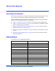
About this Manual Overview of Contents This manual is intended for users qualified in electronics or electrical engineering. Users must have a working understanding of Intelligent Platform Management Interface (IPMI). It provides information on how to control and monitor the functionality of the ATCA-7350 via IPMI and contains the following chapters and appendices: z Chapter 1, Introduction, on page 11 describes the main features of the IPMC firmware.
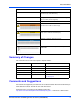
About this Manual Abbreviation Definition IPMC Intelligent Platform Management Controller IPMI Intelligent Platform Management Interface LAN Local Area Network LED Light Emitting Diode LSB Least Significant Bit LUN Logical Units MAC Media Access Control MSB Most Significant Bit NetFn IPMI Network Function in Hexadecimal OEM Original Equipment Manufacturer PICMG PCI Industrial Computer Manufacturers Group PwrOk Power OK RTM Rear-Transition Modules SDR Sensor Data Records SEL S
About this Manual Notation Description . Omission of information from example/command that is not necessary at the time being . . .. Ranges, for example: 0..4 means one of the integers 0,1,2,3, and 4 (used in registers) | Logical OR Indicates a hazardous situation which, if not avoided, could result in death or serious injury Indicates a hazardous situation which, if not avoided, may result in minor or moderate injury Indicates a property damage message No danger encountered.
About this Manual In "Area of Interest" select "Technical Documentation". Be sure to include the title, part number, and revision of the manual and tell us how you used it.
Introduction 1.1 1 Overview The ATCA-7350 provides an intelligent hardware management system as defined in the AdvancedTCA Base Specification (PICMG 3.0; AMC.0). This system implements an Intelligent Peripheral Management Controller (IPMC) based on the proprietary H8S reference design from American Megatrends Inc.
Introduction 1.2.1.1 HPM.1 Specific Firmware Upgrades IPMC Firmware Upgrade The IPMC firmware basically consists of five major parts: z Boot loader z Active and Backup IPMI firmware z Active and Backup SDR data The boot loader maintains redundant copies of the firmware in the flash memory of the ATCA7350. Each time the IPMC firmware is upgraded, the most recent firmware version is kept in flash memory and the older firmware version is overwritten by the new one.
Serial over LAN 1.2.2 Introduction Serial over LAN Serial over LAN (SOL) is an IPMI v.2.0 defined capability that allows to establish a virtual serial console connection with the payload over LAN. The serial data of the payload is transferred to the IPMC. The IPMC generates RMCP+ packets, which are routed to the ethernet controller of the base interfaces.
Introduction 1.2.7 Local System Event Log Local System Event Log The IPMC provides a local system event log (SEL). Thus, event information is stored on-board the ATCA-7350 as well. 1.2.8 External Watchdog For crisis recovery purposes the IPMI building block provides an external hardware watchdog. The IPMI firmware is reset if it does not trigger the watchdog anymore. 1.2.9 Boot Configuration Parameters The IPMC supports BIOS boot order selection via IPMI partially.
Supported Commands 2.1 2 Standard IPMI Commands The IPMC is fully compliant to the Intelligent Platform Management Interface v.1.5. This section provides information about the supported IPMI commands. 2.1.1 Global IPMI Commands The IPMC supports the following global IPMI commands. Table 2-1 Supported Global IPMI Commands 2.1.
Supported Commands Watchdog Commands Table 2-2 Supported System Interface Commands (continued) 2.1.3 Command NetFn (Request/Response) CMD Get User Name 0x06/0x07 0x46 Set User Password 0x06/0x07 0x47 Set User Payload Access 0x06/0x07 0x4C Get User Payload Access 0x06/0x07 0x4D Set Channel Security Keys 0x06/0x07 0x5C Watchdog Commands The watchdog commands are supported by blades providing a system interface and a watchdog type 2 sensor. The pre-timeout option is not supported.
FRU Inventory Commands 2.1.5 Supported Commands FRU Inventory Commands Table 2-5 Supported FRU Inventory Commands 2.1.
Supported Commands 2.1.7 Chassis Device Commands Chassis Device Commands Table 2-7 Supported Chassis Device Commands 2.1.7.1 Command NetFn (Request/Response) CMD Set System Boot Options 0x00/0x01 0x08 Get System Boot Options 0x00/0x01 0x09 System Boot Options Commands The IPMI system boot options commands allow you to control the boot process of a blade by sending boot parameters to the blade’s boot firmware (for example BIOS, U-Boot or VxWorks).
Chassis Device Commands 2.1.7.1.1 Supported Commands System Boot Options Parameter #5 This boot parameter is implemented as specified within the IPMI specification, but not all flags are supported. Table 2-9 System Boot Options Parameter #5 Data Byte Description 1 [7] - 1b = boot flags valid. The bit should be set to indicate that valid flag data is present. This bit may be automatically cleared based on the boot flag valid bit clearing parameter, above. [6] - Not supported.
Supported Commands 2.1.7.1.2 Chassis Device Commands System Boot Options Parameter #96 This boot parameter is an Emerson-specific OEM boot parameter. Its definition is given in the following table. Table 2-10 System Boot Options Parameter #96 Boot Option Parameter Data Description 1 This parameter specifies the processor ID for which the boot option is to be set. This parameter has to be 0 always for this blade.
LAN Device Commands Supported Commands There is no Set Selector or Block Selector with this command. The System Boot Options parameter #98 is non-volatile. Its parameter data remains preserved after IPMC power cycles and firmware upgrades. 2.1.7.1.4 System Boot Options #99 This parameter is an Emerson-specific OEM parameter.
Supported Commands 2.2 PICMG 3.0 Commands PICMG 3.0 Commands The Emerson IPMC is a fully compliant AdvancedTCA intelligent Platform Management Controller i.e. it supports all required and mandatory AdvancedTCA commands as defined in the PICMG 3.0 specifications. Table 2-14 Supported PICMG 3.
Emerson Specific Commands Supported Commands Table 2-14 Supported PICMG 3.0 Commands (continued) Command NetFn (Request/Response) CMD Comments Activate firmware 0x2C/0x2D 0x35 - Query self-test results 0x2C/0x2D 0x36 - Query rollback status 0x2C/0x2D 0x37 - Initiate manual rollback 0x2C/0x2D 0x38 - The firmware upgrade commands supported by the ATCA-7350 are implemented according to the PICMG HPM.1 Revision 1.0 specification. 2.
Supported Commands 2.3.1.1 Serial Output Commands Set Serial Output Command The Set Serial Output command selects the serial port output source for a serial port connector. 2.3.1.1.1 Request Data The following table lists the request data applicable to the Set Serial Output command. Table 2-16 Request Data of Set Serial Output Command Byte Data Field 1 LSB of Emerson IANA Enterprise number. A value of 0xCD has to be used. 2 Second byte of Emerson IANA Enterprise number.
Serial Output Commands 2.3.1.2.1 Supported Commands Request Data The following table lists the request data applicable to the Get Serial Output command. Table 2-18 Request Data of Get Serial Output Command Byte Data Field 1 LSB of Emerson IANA Enterprise number. A value of 0xCD has to be used. 2 Second byte of Emerson IANA Enterprise number. A value of 0x65 has to be used. 3 MSB of Emerson IANA Enterprise number. A value of 0x00 has to be used.
Supported Commands 26 Serial Output Commands ATCA-7350 Control via IPMI Programmer’s Reference (6806800H29E)
FRU Information and Sensor Data Records 3.1 3 FRU Information The ATCA-7350 supports FRU according to the PICMG 3.0 ATCA specification. The ATCA7350 supports six FRUs, including: z FRU0: on the ATCA-7350 z FRU1: RTM-ATCA-7350 z FRU2-FRU3: for daughter cards on the RTM-ATCA-7350 z FRU6: SOL daughter card on the ATCA-7350 FRU0 and FRU1 are managed FRUs, whereas other FRUs are unmanaged ones. Table 3-1 shows the FRU data format of RU0-FRU6.
FRU Information and Sensor Data Records MAC Address Record addresses. The format of the record is described in the following tables. Table 3-2 Emerson MAC Address Record Offset Length Description 0 1 Record Type ID. A value of 0xC0 1 1 End of List/Version [7] End of List. Set to 01b for the last record [6:4] Reserved. Write as 0b0000. [3:0] Record format version. Write as 0x2. 2 1 Record Length 3 1 Record Checksum. Holds the zero checksum of the record 4 1 Header Checksum.
Sensor Data Records 3.3 FRU Information and Sensor Data Records Sensor Data Records The sensors available on the ATCA-7350 are shown in the table below. Table 3-5 IPMI Sensors Overview Sensor Name Sensor Type Sensor Number Detailed SDR Description +12VCC Voltage 0x07 See Table 3-6 on page 30 +3.3VCC Voltage 0x05 See Table 3-7 on page 30 +3.
FRU Information and Sensor Data Records Sensor Data Records The following tables describe all on-board IPMI sensors in detail.
Sensor Data Records FRU Information and Sensor Data Records Table 3-7 +3.3VCC Sensor (continued) Feature Raw Value Description Assertion Event Mask(Byte 15) 0x95 - Assertion Event Mask(Byte 16) 0x0A - Deassertion Event Mask(Byte 17) 0x95 - Deassertion Event Mask(Byte 18) 0x0A - Threshold Mask(Byte 19) 0x3F - Threshold Mask(Byte 20) 0x3F - Base Unit 0x04 Volts Nominal Reading 0xBF 3.3 Upper non-recoverable threshold 0xD6 3.7 Upper critical threshold 0xD1 3.
FRU Information and Sensor Data Records Sensor Data Records Table 3-8 +3.3VSB Sensor (continued) Feature Raw Value Description Nominal Reading 0xC2 3.3 Upper non-recoverable threshold 0xD9 3.69 Upper critical threshold 0xD5 3.62 Upper non-critical threshold 0xD0 3.54 Lower non-recoverable threshold 0xAB 2.91 Lower critical threshold 0xB0 2.99 Lower non-critical threshold 0xB5 3.
Sensor Data Records FRU Information and Sensor Data Records Table 3-9 +5VCC Sensor (continued) Feature Raw Value Description Rearm mode 0x01 Auto Hysteresis Support 0x02 Readable and Setable Threshold Access Support 0x02 Readable and Setable Event Message Control 0x00 Per Threshold / Discrete State Reading Definition Analog reading byte Analog sensor reading Feature Raw Value Description Sensor Name +5VSB - Sensor LUN 0x00 - Sensor Number 0x06 - Entity ID 0xA0 PICMG Front B
FRU Information and Sensor Data Records Sensor Data Records Table 3-11 -48V Power1 Sensor Feature Raw Value Description Sensor Name -48V Power1 - Sensor LUN 0x00 - Sensor Number 0x0C - Entity ID 0xA0 PICMG Front Board Sensor Type 0x08 Power Supply Event/Reading Type 0x6F Discrete (sensor-specific) Assertion Event Mask(Byte 15) 0x03 - Assertion Event Mask(Byte 16) 0x00 - Assertion Events - - - Event Offset: 0 Presence detected - Event Offset: 1 Power supply failure detect
Sensor Data Records FRU Information and Sensor Data Records Table 3-12 -48V Power2 Sensor (continued) Feature Raw Value Description Deassertion Event Mask(Byte 17) 0x00 - Deassertion Event Mask(Byte 18) 0x00 - Threshold Mask(Byte 19) 0x03 - Threshold Mask(Byte 20) 0x00 - Base Unit 0x00 (unspecified) Rearm mode 0x01 Auto Hysteresis Support 0x00 No Hysteresis or unspecified Threshold Access Support 0x00 No Thresholds Event Message Control 0x00 Per Threshold / Discrete State Rea
FRU Information and Sensor Data Records Sensor Data Records Table 3-14 BIOS Bank Sensor Feature Raw Value Description Sensor Name BIOS Bank - Sensor LUN 0x00 - Sensor Number 0x19 - Entity ID 0xA0 PICMG Front Board Sensor Type 0xD2 Emerson-specific Discrete Digital Event/Reading Type 0x6F Discrete (sensor-specific) Assertion Event Mask(Byte 15) 0x0F - Assertion Event Mask(Byte 16) 0x00 - Assertion Events - - - Sensor Offset: 0 Last Boot from BIOS Bank A - Sensor Offset: 1
Sensor Data Records FRU Information and Sensor Data Records Table 3-15 BMC POST ERROR Sensor (continued) Feature Raw Value Description - Event Offset: 5 FRU failure Deassertion Event Mask(Byte 17) 0x31 - Deassertion Event Mask(Byte 18) 0x00 - Deassertion Events - - - Event Offset: 0 Sensor access degraded or unavailable - Event Offset: 4 Sensor failure - Event Offset: 5 FRU failure Threshold Mask(Byte 19) 0x31 - Threshold Mask(Byte 20) 0x00 - Base Unit 0x00 (unspecified) R
FRU Information and Sensor Data Records Sensor Data Records Table 3-16 Boot Errors Sensor (continued) Feature Raw Value Description Threshold Access Support 0x00 No Thresholds Event Message Control 0x00 Per Threshold / Discrete State Reading Definition - See IPMI 1.
Sensor Data Records FRU Information and Sensor Data Records Table 3-18 CPU0 Status Sensor Feature Raw Value Description Sensor Name CPU0 Status - Sensor LUN 0x00 - Sensor Number 0x0E - Entity ID 0x03 - Sensor Type 0x07 Processor Event/Reading Type 0x6F Discrete (sensor-specific) Assertion Event Mask(Byte 15) 0x83 - Assertion Event Mask(Byte 16) 0x01 - Assertion Events - - - Event Offset: 0 Internal error (IERR) - Event Offset: 1 Thermal Trip - Event Offset: 7 Processo
FRU Information and Sensor Data Records Sensor Data Records Table 3-19 CPU1 Core Rem Sensor (continued) Feature Raw Value Description Deassertion Event Mask(Byte 18) 0x0A - Threshold Mask(Byte 19) 0x3F - Threshold Mask(Byte 20) 0x3F - Base Unit 0x01 deg.
Sensor Data Records FRU Information and Sensor Data Records Table 3-20 CPU1 Status Sensor (continued) Feature Raw Value Description Threshold Mask(Byte 20) 0x01 - Base Unit 0x00 (unspecified) Rearm mode 0x01 Auto Hysteresis Support 0x00 No Hysteresis or unspecified Threshold Access Support 0x00 No Thresholds Event Message Control 0x00 Per Threshold / Discrete State Reading Definition - - Feature Raw Value Description Sensor Name CPU Inlet Temp - Sensor LUN 0x00 - Sensor Nu
FRU Information and Sensor Data Records Sensor Data Records Table 3-22 FBD Inlet Temp Sensor Feature Raw Value Description Sensor Name FBD Inlet Temp - Sensor LUN 0x00 - Sensor Number 0x02 - Entity ID 0xA0 PICMG Front Board Sensor Type 0x01 Temperature Event/Reading Type 0x01 Threshold Assertion Event Mask(Byte 15) 0x95 - Assertion Event Mask(Byte 16) 0x0A - Deassertion Event Mask(Byte 17) 0x95 - Deassertion Event Mask(Byte 18) 0x0A - Threshold Mask(Byte 19) 0x3F - Thre
Sensor Data Records FRU Information and Sensor Data Records Table 3-23 FRU Hot Swap Sensor (continued) Feature Raw Value Description Assertion Event Mask(Byte 16) 0x00 - Deassertion Event Mask(Byte 17) 0x00 - Deassertion Event Mask(Byte 18) 0x00 - Threshold Mask(Byte 19) 0xFF - Threshold Mask(Byte 20) 0x00 - Base Unit 0x00 (unspecified) Rearm mode 0x01 Auto Hysteresis Support 0x00 No Hysteresis or unspecified Threshold Access Support 0x00 No Thresholds Event Message Control
FRU Information and Sensor Data Records Sensor Data Records Table 3-24 FW Progress Sensor (continued) Feature Raw Value Description Threshold Access Support 0x00 No Thresholds Event Message Control 0x00 Per Threshold / Discrete State Reading Definition - See IPMI 1.
Sensor Data Records FRU Information and Sensor Data Records Table 3-26 HD Env Temp Sensor (continued) Feature Raw Value Description Sensor Number 0x03 - Entity ID 0xA0 PICMG Front Board Sensor Type 0x01 Temperature Event/Reading Type 0x01 Threshold Assertion Event Mask(Byte 15) 0x95 - Assertion Event Mask(Byte 16) 0x0A - Deassertion Event Mask(Byte 17) 0x95 - Deassertion Event Mask(Byte 18) 0x0A - Threshold Mask(Byte 19) 0x3F - Threshold Mask(Byte 20) 0x3F - Base Unit 0x0
FRU Information and Sensor Data Records Sensor Data Records Table 3-27 IPMB Link State Sensor (continued) Feature Raw Value Description Deassertion Event Mask(Byte 18) 0x00 - Threshold Mask(Byte 19) 0x0F - Threshold Mask(Byte 20) 0x00 - Base Unit 0x00 (unspecified) Rearm mode 0x01 Auto Hysteresis Support 0x00 No Hysteresis or unspecified Threshold Access Support 0x00 No Thresholds Event Message Control 0x00 Per Threshold / Discrete State Reading Definition - See PICMG 3.
Sensor Data Records FRU Information and Sensor Data Records Table 3-28 Log Disabled Sensor (continued) Feature Raw Value Description Threshold Access Support 0x00 No Thresholds Event Message Control 0x00 Per Threshold / Discrete State Reading Definition - - Table 3-29 PwrOk Sig. Drop Sensor Feature Raw Value Description Sensor Name PwrOk Sig.
FRU Information and Sensor Data Records Sensor Data Records Table 3-30 RTM Handle Sensor (continued) Feature Raw Value Description Event/Reading Type 0x6F Discrete (sensor-specific) Assertion Event Mask (Byte 15) 0x0F - Assertion Event Mask (Byte 16) 0x00 - Assertion Events - - - Sensor Offset: 0 Handle state ok (both in open/close state) - Sensor Offset: 1 Upper handle closed - Sensor Offset: 2 Lower handle closed Deassertion Event Mask (Byte 17) 0x00 - Deassertion Event Mask (
Sensor Data Records FRU Information and Sensor Data Records Table 3-31 RTM HS Sensor (continued) Feature Raw Value Description Rearm mode 0x01 Auto Hysteresis Support 0x00 No Hysteresis or unspecified Threshold Access Support 0x00 No Thresholds Event Message Control 0x00 Per Threshold / Discrete State Reading Definition - See PICMG 3.
FRU Information and Sensor Data Records Sensor Data Records Table 3-33 Ver Change Sensor (continued) Feature Raw Value Description Entity ID 0xA0 PICMG Front Board Sensor Type 0x2B Version Change Event/Reading Type 0x6F Discrete (sensor-specific) Assertion Event Mask(Byte 15) 0x81 - Assertion Event Mask(Byte 16) 0x00 - Assertion Events - - - Event Offset: 7 Software or firmware change detected with associated entity was successful.
Sensor Data Records FRU Information and Sensor Data Records Table 3-34 Watchdog Sensor (continued) Feature Raw Value Description Deassertion Event Mask(Byte 18) 0x00 - Threshold Mask(Byte 19) 0x0F - Threshold Mask(Byte 20) 0x00 - Base Unit 0x00 (unspecified) Rearm mode 0x01 Auto Hysteresis Support 0x00 No Hysteresis or unspecified Threshold Access Support 0x00 No Thresholds Event Message Control 0x00 Per Threshold / Discrete State Reading Definition - See IPMI 1.
FRU Information and Sensor Data Records 52 Sensor Data Records ATCA-7350 Control via IPMI Programmer’s Reference (6806800H29E)
SOL Module Configuration 4.1 4 Introduction This chapter includes the following sections: 4.2 z Configure the SOL z Enable SOL load z Setup a SOL session z Query the configuration of SOL z Configure the SOL mode in OS Configure the SOL Before the configuration, the IPMC has no user or IP address, so you cannot connect to the IPMC through IPMITOOL. In this case, you need to use IPMI commands through the IPMB channel of the shelf managers to configure the SOL and set the IPMC.
SOL Module Configuration Enable SOL Load "90" is the IPMB address of the blade. The IP addresses of the two channels cannot be set to be in the same network segment. Otherwise, the settings fail. 2. Set the subnet mask of the two channels. Use the command Set LAN Configuration Parameters of IPMI2.0 with Parameter selector of 6. The value of Parameter selector is 6. See table 23-4 in section 23.2 of the IPMI 2.0 specification.
Setup SOL Session SOL Module Configuration The value of Parameter selector is 1. See table 26-5 in section 26.3 of the IPMI 2.0 specification. On Emerson shelf manager, enable the SOL of channel 1. ipmicmd -k "0 90 0 0c 21 01 01 01" smi 0 4.4 Setup SOL Session After the previous seven steps, you can set up a session or an SOL connection to the IPMC through IPMITOOL. You can use the commands provided by IPMITOOL to directly configure the SOL for the IPMC.
SOL Module Configuration Query the Configuration of SOL See table 22-27 in section 22.23 of the IPMI 2.0 specification. For example, on Emerson shelf manager, query the information about channel 1. ipmicmd -k "0 90 0 06 41 01 40" smi 0 5. Query the user right. Use the command Get User Access. See table 22-31 in section 22.27 of the IPMI 2.0 specification. For example, on Emerson shelf manager, query the right of user 2 in channel 1.
Configure the SOL Module in OS 4.6 SOL Module Configuration Configure the SOL Module in OS All the configurations and the queries example above are carried out on the shelf manager of Emerson. If you want to do it in OS with standard IPMI tools by sending the IPMI command to the IPMC through KCS, some parameters of the command should be modified.
SOL Module Configuration 58 Configure the SOL Module in OS ATCA-7350 Control via IPMI Programmer’s Reference (6806800H29E)
A Related Documentation A.1 A Emerson Network Power - Embedded Computing Documents The Emerson Network Power - Embedded Computing publications listed below are referenced in this manual. You can obtain electronic copies of Emerson Network Power - Embedded Computing publications by contacting your local Emerson sales office. For documentation of final released (GA) products, you can also visit the following website: http://www.emersonnetworkpowerembeddedcomputing.
Related Documentation 60 Related Specifications ATCA-7350 Control via IPMI Programmer’s Reference (6806800H29E)