Precision Cooling For Business-Critical Continuity™ Liebert Mini-Mate2™–1 & 1.5 Ton (3.
TABLE OF CONTENTS 1.0 INTRODUCTION . . . . . . . . . . . . . . . . . . . . . . . . . . . . . . . . . . . . . . . . . . . . . . . . . . . . . . . . . .1 1.1 Designed to Match Computer and Electronic Equipment Needs—From Installation to Operation . . . . . . . . . . . . . . . . . . . . . . . . . . . . . . . . . . . . . . . . . . . . . . . . . . . . . . . . . . . . . . . . . . 1 2.0 STANDARD FEATURES—1 & 1.5 TON SYSTEMS . . . . . . . . . . . . . . . . . . . . . . . . . . . . . . . . .2 2.
GUIDE SPECIFICATIONS FOR LIEBERT MINI-MATE2—1- AND 1.5-TON SYSTEMS . . . . . . . . . . . . . . 35 1.0 General . . . . . . . . . . . . . . . . . . . . . . . . . . . . . . . . . . . . . . . . . . . . . . . . . . . . . . . . . . . . . 35 1.1 1.2 1.3 1.4 Summary. . . . . . . . . . . . . . . . . . . . . . . . . . . . . . . . . . . . . . . . . . . . . . . . . . . . . . . . . . . . . . . . . . Design Requirements . . . . . . . . . . . . . . . . . . . . . . . . . . . . . . . . . . . . . . . . . . . . . . . . . .
TABLES Table 1 Table 2 Table 3 Table 4 Table 5 Table 6 Table 7 Table 8 Table 9 Table 10 Table 11 Table 12 Table 13 Table 14 Table 15 Table 16 Table 17 Table 18 Table 19 Air-cooled data, 60Hz . . . . . . . . . . . . . . . . . . . . . . . . . . . . . . . . . . . . . . . . . . . . . . . . . . . . . . . . . . . . . 9 Unit net weights—Air-cooled units . . . . . . . . . . . . . . . . . . . . . . . . . . . . . . . . . . . . . . . . . . . . . . . . . 12 Net weight, condenser fan module . . . . . . . . . . . . . .
iv
Introduction 1.0 INTRODUCTION 1.1 Designed to Match Computer and Electronic Equipment Needs—From Installation to Operation Installed above the ceiling, the Liebert Mini-Mate2 system controls the cooling, humidity and air distribution required by sensitive electronic equipment. A range of sizes and configurations are available to meet site needs. The Liebert Mini-Mate2 is also easy to use.
Standard Features—1 & 1.5 Ton Systems 2.0 STANDARD FEATURES—1 & 1.5 TON SYSTEMS 2.1 Self-Contained Systems The self-contained system is designed for ceiling installation. The cabinet and chassis are constructed of heavy gauge galvanized steel. The unit can be serviced using only one side, increasing its versatility in mounting locations. Mounting brackets are factory-attached to the cabinet. Internal cabinet insulation meets ASHRAE 62.
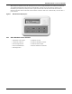
Standard Features—1 & 1.5 Ton Systems The wall-box is field-wired to the microprocessor control using standard four-conductor thermostat wire (field-supplied). The temperature and humidity sensors are in the wall box, which can be installed up to 300 feet (91.4m) from the evaporator unit. The unit-mounted control board also includes common alarm terminals and shutdown terminals. The unit automatically restarts after a power failure. Figure 1 2.4.
Optional Factory-Installed Features—Self-Contained and Evaporator Units 3.0 OPTIONAL FACTORY-INSTALLED FEATURES—SELF-CONTAINED AND EVAPORATOR UNITS 3.1 Reheat Electric reheat includes 304/304 stainless steel finned tubular reheat elements for added durability and corrosion resistance with a high limit safety switch. SCR Reheat provides tight temperature control by rapidly pulsing the 304/304 stainless steel reheat elements in small increments.
Optional Factory-Installed Features—Self-Contained and Evaporator Units 3.5 Free-Cooling Free-cooling option includes separate cooling coil, three-way, slow-close valve and separate supply and return piping. Free-cooling is activated when the water temperature reaches a field-adjustable temperature, typically 45°F (7°C). The valve is rated for 300psi (2068kPa) working pressure.
Ship-Loose Accessories—Field-Installed 4.0 SHIP-LOOSE ACCESSORIES—FIELD-INSTALLED Supply and Return Grille Kit includes supply and return grilles, 1" x 20" x 20" (25mm x 508mm x 508mm) MERV 8 rated filter to ASHRAE 52.2-2007, for installation into a 2ft. x 4ft. (610mm x 1220mm) ceiling grid. Duct Kit includes return air filter box with 1" duct collar, 1" duct collar for supply air, and air blockoff plates.
Ship-Loose Accessories—Field-Installed The Liebert ENV-DO™ interface card provides 16 discrete outputs, corresponding to status and major alarm conditions of Environmental units. The Liebert ENV-DO-ENCL1 packages one Environmental DO interface card in its own steel enclosure and the ENV-DO-ENCL2 packages two Environmental DO interface cards in one enclosure for installation external to the Liebert Mini-Mate2™. The self-contained kit includes an external 120VAC-to-24VAC power transformer.
Flexible Configurations 5.
Air-Cooled Systems—Capacities and Dimensions 6.0 Table 1 AIR-COOLED SYSTEMS—CAPACITIES AND DIMENSIONS Air-cooled data, 60Hz MMD12A MMD12E MMD18A MMD18E Self-Contained Split System Self-Contained Split System 3.70 (12,600) 3.60 (12,300) 3.50 (12,000) 3.25 (11,100) 3.45 (11,700) 3.00 (10,200) 4.25 (14,400) 3.95 (13,500) 4.00 (13,700) 3.55 (12,100) 3.90 (13,300) 3.25 (11,100) 5.55 (18,900) 5.30 (18,100) 5.30 (18,100) 4.75 (16,300) 5.15 (17,600) 4.40 (15,000) 5.65 (19,300) 5.35 (18,300) 5.
Air-Cooled Systems—Capacities and Dimensions Figure 4 General arrangement—self contained air-cooled system High Pressure Switch Compressor Condenser Coil External Equalizer Filter Drier Sensing Bulb Hot Gas Bypass Solenoid Valve Evaporator Coil Hot Gas Bypass Control Valve Expansion Valve DPN000168 Rev.
Air-Cooled Systems—Capacities and Dimensions Figure 6 General arrangement—Self-contained air-cooled unit with hot gas reheat High Pressure Switch Solenoid Valve Provided With Optional Hot Gas Reheat Check Valve Compressor Condenser Coil External Equalizer Filter Drier Sensing Bulb Hot Gas Reheat Coil (Optional) Hot Gas Bypass Control Valve Expansion Valve NOTE: Hot gas reheat is available only on self-contained “DX” modules. Air-cooled piping shown, also available on water and glycol models.
Air-Cooled Systems—Capacities and Dimensions Figure 8 Dimensions—Air-cooled, self-contained and split systems Threaded Rod Centers Left End 56"(1422mm) Threaded Rod Centers " 2 7 m) m 6 (68 Condenser blower box location for Self-Contained, Air-Cooled Units only. See Figure 11 for dimensions. Removable Access Panels Customer-supplied threaded rods for module support from ceiling (typ. 4) 3/8" (10mm) holes for module rigging. (typ. 2 each end) 1" (25.
Air-Cooled Systems—Capacities and Dimensions Figure 9 Dimensions—Return filter box, all systems 20-1/4" (514mm) 7-5/8" (194mm) 8" (203mm) 2-1/4" (57mm) 14" (357mm) 16" (406mm) 1-1/4" (32mm) 3/4" (19mm) Flange 18" (457mm) 1" (25.4mm) Shaded area indicates a recommended clearance of 30" (762mm) for component access and removal. DPN000173 Rev.
Air-Cooled Systems—Capacities and Dimensions Figure 11 Dimensions—Condenser fan module 20" (508mm) High & Low Voltage Wire Harness see unit schematic for wiring. 4-11/16" (119mm) Blower Motor & Controller access cover 17-1/4" (438mm) Blower & Motor Assembly Fan Speed Controller 12" (305mm) Capillary tube from fan speed controller Screw onto access valve in discharge line (inside ceiling unit). Shaded area indicates a recommended clearance of 24" (610mm) for component access and removal.
Air-Cooled Systems—Capacities and Dimensions Figure 12 Dimensions—Air-cooled systems, outdoor condensing unit Fan Rotation CCW (left side) Removable (right) panel for access to refrigeration component A Right Air Discharge Left Air Intake B Shaded area indicates a recommended clearance of 24" (610mm) for component access and removal. C Shaded area indicates a minimum clearance of 18" (457mm) for proper air flow Table 4 Shaded area indicates a minimum clearance of 18" (457mm) for proper air flow.
Water/Glycol Systems—Capacities and Dimensions 7.0 Table 5 WATER/GLYCOL SYSTEMS—CAPACITIES AND DIMENSIONS Water/Glycol data, 60Hz MMD14W Evaporator Model (Self-Contained) MMD20W Water-Cooled Glycol-Cooled Water-Cooled Glycol-Cooled Condensing Unit Fluid DX Evaporator- Net Capacity Data - kW (Btu/hr) @ High Speed CFM 80°F DB, 62.8°F WB (26.7°C DB, Total 4.05 (13,800) 3.50 (11,900) 6.40 (21,800) 5.20 (17,800) 17.1°C WB) 38% RH Sensible 3.85 (13,100) 3.45 (11,800) 5.80 (19,800) 5.
Water/Glycol Systems—Capacities and Dimensions Figure 13 General arrangement—Self-contained water/glycol-cooled system High Pressure Switch Compressor Tube-in-Tube Condenser External Equalizer Evaporator Coil Tube-in-Tube Condenser Water/Glycol Return Line Filter Drier Sensing Bulb Water/Glycol Supply Line Fluid Return Hot Gas Bypass From Unit Solenoid Valve Hot Gas Bypass Control Valve Fluid Supply To Unit Expansion Shut- Off * Valve Valve Shutoff 2-Way Water Valve * Regulating Valve Hose Bibs
Water/Glycol Systems—Capacities and Dimensions Figure 15 General arrangement, Self-contained water/glycol-cooled unit with hot gas reheat High Pressure Switch Solenoid Valve Provided With Optional Hot Gas Reheat Check Valve Compressor Condenser Coil External Equalizer Filter Drier Sensing Bulb Hot Gas Reheat Coil (Optional) NOTE: Hot gas reheat is available only on self-contained “DX” modules. Air-cooled piping shown, also available on water and glycol models.
Water/Glycol Systems—Capacities and Dimensions Figure 16 Dimensions - Water/glycol self-contained units Threaded Rod Centers Left End 56"(1422mm) Threaded Rod Centers " 2 7 m) m 6 (68 Condenser blower box location for Self-Contained, Air-Cooled Units only. See Figure 11 for dimensions. Removable Access Panels Customer-supplied threaded rods for module support from ceiling (typ. 4) 3/8" (10mm) holes for module rigging. (typ. 2 each end) 1" (25.
Water/Glycol Systems—Capacities and Dimensions Figure 17 Dimensions—Return filter box, all systems 20-1/4" (514mm) 7-5/8" (194mm) 8" (203mm) 2-1/4" (57mm) 14" (357mm) 16" (406mm) 1-1/4" (32mm) 3/4" (19mm) Flange 18" (457mm) 1" (25.4mm) Shaded area indicates a recommended clearance of 30" (762mm) for component access and removal. DPN000173 Rev.
Chilled Water Systems—Capacities and Dimensions 8.0 Table 7 CHILLED WATER SYSTEMS—CAPACITIES AND DIMENSIONS Chilled water data, 50/60Hz Model Number, 50 & 60 Hz MMD23C/MMD22C Net Capacity Data - kW (Btu/hr) based on 45°F (7.2°C) EWT & 10°F (5.6°C) temp. rise Total 4.85 (16,400) 80°F DB, 62.8°F WB (26.7°C DB, 17.1°C WB) 38% RH Sensible 4.80 (16,300) Flow Rate - GPM (l/m) 3.4 (12.9) Pressure Drop - ft. water (kPa) 10.7 (32.0) Total 3.85 (13,100) 75°F DB, 61°F WB (23.9°C DB, 16.1°C WB) 45% RH Sensible 3.
Chilled Water Systems—Capacities and Dimensions Table 8 Capacity correction factors (based on 10°F (5.6°C) water rise) 72°F (22.2°C) 50% RH 75°F (23.9°C) 45% RH EWT TCC SCC TCC SCC 42°F (5.6°C) 43°F (6.1°C) 44°F (6.7°C) 45°F (7.2°C) 46°F (7.8°C) 47°F (8.3°C) 48°F (8.9°C) 49°F (9.4°C) 1.30 1.19 1.09 1.00 0.94 0.88 0.82 0.75 1.14 1.10 1.05 1.00 0.95 0.89 0.82 0.75 1.25 1.17 1.08 1.00 0.95 0.90 0.85 0.80 1.11 1.07 1.04 1.00 0.96 0.90 0.85 0.
Chilled Water Systems—Capacities and Dimensions Figure 21 Dimensions—Chilled water unit Threaded Rod Centers Left End 56"(1422mm) Threaded Rod Centers " 2 7 m) m 6 (68 Condenser blower box location for Self-Contained, Air-Cooled Units only. See Figure 11 for dimensions. Removable Access Panels Customer-supplied threaded rods for module support from ceiling (typ. 4) 3/8" (10mm) holes for module rigging. (typ. 2 each end) 1" (25.
Chilled Water Systems—Capacities and Dimensions Figure 22 Dimensions—Return filter box, all systems 20-1/4" (514mm) 7-5/8" (194mm) 8" (203mm) 2-1/4" (57mm) 14" (357mm) 16" (406mm) 1-1/4" (32mm) 3/4" (19mm) Flange 18" (457mm) 1" (25.4mm) Shaded area indicates a recommended clearance of 30" (762mm) for component access and removal. DPN000173 Rev.
Electrical Data 9.0 ELECTRICAL DATA Table 10 Electrical data, self-contained air-cooled units, 60Hz Base Evaporator Model Number 208/230 - 1Ph - 60Hz 277 - 1Ph - 60Hz MM*12A MM*18A MM*12A MM*18A FLA 8.2 14.2 6.8 11.8 WSA 9.4 16.9 7.8 14.0 OPD 15 25 15 20 FLA 27.0 33.0 23.1 28.1 WSA 32.9 40.4 28.2 34.4 OPD 35 45 30 35 FLA 27.0 33.0 23.1 28.1 WSA 32.9 40.4 28.2 34.4 OPD 35 45 30 35 FLA 13.0 19.0 10.4 15.4 WSA 14.2 21.7 11.4 17.
Electrical Data Table 11 Electrical Data—Self-contained water/glycol-cooled units, 60Hz Base Evaporator Model Number 208/230 - 1Ph - 60Hz 277 - 1Ph - 60Hz MM*14W MM*20W MM*14W MM*20W FLA 6.1 12.1 5.3 10.3 WSA 7.3 14.8 6.3 12.5 OPD 15 25 15 20 FLA 24.9 30.9 21.6 26.6 WSA 30.8 38.3 26.7 32.9 OPD 35 40 30 35 FLA 24.9 30.9 21.6 26.6 WSA 30.8 38.3 26.7 32.9 OPD 35 40 30 35 FLA 10.9 16.9 8.9 13.9 WSA 12.1 19.6 9.9 16.
Electrical Data Table 12 Electrical data—Split-evaporator or self-contained chilled water units, 50/60 Hz 208/230 - 1Ph - 60Hz 277 - 1Ph - 60Hz 220- 1Ph - 50Hz MM*12E; MM*18E; MM*23C MM*12E; MM*18E; MM*23C MM*22C FLA 1.4 1.4 1.4 WSA 1.8 1.8 — OPD 15 15 — FLA 20.2 17.7 20.2 WSA 25.3 22.1 — OPD 30 25 — FLA 20.2 17.7 20.2 WSA 25.3 22.1 — OPD 30 25 — FLA 6.2 5.0 6.0 WSA 7.8 6.3 — OPD 15 15 — FLA 25.0 21.3 24.8 WSA 31.3 26.
Refrigerant Piping 10.0 REFRIGERANT PIPING Table 14 Refrigerant charge Model # 60Hz Unit Type 50Hz Charge R-407C * oz (kg) Self Contained-Air MM*12A/F — 42 (1.19) Self Contained-Water MM*14W/G — 27 (0.77) Split Evaporator-Air MM*12E/K — 3 (0.085) Self Contained-Air MM*18A/F — 49 (1.39) Self Contained-Water MM*20W/G — 28 (0.79) Split Evaporator-Air MM*18E/K — 4 (0.11) Split Condensing Unit PFH014A-_L7 — 134 (3.80) Split Condensing Unit PFH020A-_L7 — 134 (3.
Refrigerant Piping Table 18 Refrigerant charge in Liebert pre-charged R-407C line sets Line Size, in. 3/8 liquid 5/8 or 7/8 suction Table 19 Length, ft. (m) Charge R-407C, oz (kg) 15 (4.5) 5 (0.14) 30 (9) 10 (0.28) 15 (4.5) 5 (0.14) 30 (9) 10 (0.28) Equivalent lengths for various pipe fittings, ft (m) Copper Pipe OD, in. 90 Degree Elbow Copper 90 Degree Elbow Cast 45 Degree Elbow Tee Gate Valve Globe Valve Angle Valve 1/2 0.8 (0.24) 1.3 (0.39) 0.4 (0.12) 2.5 (0.76) 0.26 (0.
Glycol Loop Piping 11.0 GLYCOL LOOP PIPING Contact Emerson Application Engineering for assistance in choosing correct drycooler models. Refer to Figure 25. Figure 25 Heat rejection loop, multiple drycoolers and multiple indoor units Expansion Tank ______ Gal. (L) HP GPM (l/s) ft. ____(kW) ____ Per Pump @ ____(kPa) FS PUMP PACKAGE Drycooler No.
Model Number Nomenclature—All Systems 12.
Model Number Nomenclature—All Systems Figure 27 Model number nomenclature—Split evaporator air-cooled units Liebert Mini-Mate2 Humidification H = Canister Humidifier 0 = No Humidifier R = Remote Humidifier Contact J = Canister Humidifier and Remote Humidifier Contact D = Disconnect Switch 0 = No Disconnect Switch Nominal Capacity, kBtu/hr 12 & 18 (60Hz) MM D 18 E 7 P H E 0 A Unit Type E = Split Evaporator K = Split Evaporator with Free-Cooling Refrigerant 7 = R-407C (E/K Unit Types) Supply Powe
Model Number Nomenclature—All Systems Figure 29 Model number nomenclature—Self-contained, water/glycol-cooled units Liebert Mini-Mate2 D = Disconnect Switch 0 = No Disconnect Switch Humidification H = Canister Humidifier 0 = No Humidifier R = Remote Humidifier Contact J = Canister Humidifier and Remote Humidifier Contact Nominal Capacity, kBtu/hr 14 & 20 (60 Hz) Unit Type W = Water/Glycol-Cooled G = Water/Glycol-Cooled with Free-Cooling Coil MM D 20 W 2 P H E 7 A Valve Type 2 = 2-Way Std.
Model Number Nomenclature—All Systems Figure 30 Model number nomenclature—Chilled water units Liebert Mini-Mate2 Humidification H = Canister Humidifier 0 = No Humidifier R = Remote Humidifier Contact J = Canister Humidifier and Remote Humidifier Contact D = Disconnect Switch 0 = No Disconnect Switch Nominal Capacity, kBtu/hr 23 (60Hz) 22 (50Hz) MM D 23 C 2 P H E 0 A Unit Type C = Chilled Water Valve Type 2 = 2-Way Valve (Std Close-off) D = 2-Way Valve (High Close-off) Reheat Type 0 = No Reheat
Guide Specifications for Liebert Mini-Mate2—1- and 1.5-Ton Systems GUIDE SPECIFICATIONS FOR LIEBERT MINI-MATE2—1- AND 1.5-TON SYSTEMS 1.0 GENERAL 1.1 Summary These specifications describe requirements for an environmental control system. The system shall be designed to control temperature and relative humidity conditions within the room. The manufacturer shall design and furnish all equipment in the quantities and configurations shown on the project drawings.
Guide Specifications for Liebert Mini-Mate2—1- and 1.5-Ton Systems 2.1.2 Air Distribution The air distribution system shall be constructed with a quiet, direct-drive fan assembly equipped with double-inlet blower, self-aligning ball bearings and lifetime lubrication. Fan motor shall be 1/5hp (149W), permanent-split capacitor, high efficiency type, equipped with two speeds for air flow modulation for precise dehumidification control. Dehumidification shall utilize the lower fan speed.
Guide Specifications for Liebert Mini-Mate2—1- and 1.5-Ton Systems 2.1.4 Alarms 2.1.4.1 Unit Alarm The control system shall monitor unit operation and activate an audible and visual alarm in the event of the following factory preset alarm conditions: • • • • • • • • High Temperature Low Temperature High Humidity Low Humidity High Water Alarm - Lockout Unit Operation High Head Pressure Loss of Power Compressor Short Cycle 2.1.4.
Guide Specifications for Liebert Mini-Mate2—1- and 1.5-Ton Systems 2.2 Direct Expansion Self-Contained System Components 2.2.1 Refrigeration System The refrigeration system shall consist of a (scroll) (rotary) compressor with vibration isolating grommets, evaporator coil, condenser coil, externally equalized thermostatic expansion valve, high pressure safety switch, filter drier, hot gas bypass circuit, factory R-407C refrigerant charge and externally equalized expansion valve.
Guide Specifications for Liebert Mini-Mate2—1- and 1.5-Ton Systems 2.2 Direct Expansion Split System Components 2.2.1 Evaporator Unit The evaporator section shall include evaporator coil, thermostatic expansion valve and filter drier. The evaporator coil shall have 2.4 sq.ft. (0.23 sq.m) face area, __ rows deep. It shall be constructed of copper tubes and aluminum fins and have a maximum face velocity of ___ ft. per minute (____ m/s) at ___ CFM ( ____ CMH).
Guide Specifications for Liebert Mini-Mate2—1- and 1.5-Ton Systems 2.3.5 Hot Gas Reheat The complete hot gas reheat system shall include a copper tube, aluminum fin coil, three-way solenoid valve, and refrigerant check valve. The capacity of the coil shall be ______ Btu/hr (kW). Hot gas reheat shall operate only during dehumidification and capacity shall be offset by cooling coil capacity. Hot gas reheat shall not be used for space heating. 2.3.
Guide Specifications for Liebert Mini-Mate2—1- and 1.5-Ton Systems 2.4.5 Condensate Pump The condensate pump shall have the capacity of _____ GPH (___ l/h) at ___ ft. head (___ kPa). It shall be complete with integral float switch, discharge check valve, pump, motor assembly and reservoir. A secondary float switch shall be provided to permit field wiring to the unit control to shut down the evaporator upon a high water level condition. 2.4.
Guide Specifications for Liebert Mini-Mate2—1- and 1.5-Ton Systems 3.0 EXECUTION 3.1 Installation of Air Conditioning Unit 3.1.1 General Install air conditioning unit in accordance with manufacturer's installation instructions. Install unit plumb and level, firmly anchored in location indicated, and maintain manufacturer's recommended clearances. 3.1.2 Electrical Wiring Install and connect electrical devices furnished by manufacturer but not specified to be factorymounted.
Guide Specifications for Liebert Mini-Mate2—1- and 1.
Guide Specifications for Liebert Mini-Mate2—1- and 1.
Ensuring The High Availability Of Mission-Critical Data And Applications. Emerson Network Power, a business of Emerson (NYSE:EMR), is the global leader in enabling Business-Critical Continuity™ from grid to chip for telecommunication networks, data centers, health care and industrial facilities.